10.3 DESIGN INTEGRATION FOR ENGINE SYSTEM CALIBRATION
Design Requirements for the Calibration of an Engine System
Because of unavoidable mechanical tolerances, it may be expected that the operating characteristics and performance of the various engine system components will deviate somewhat from their nominal design value. A certain amount of calibration is always required for these components, as well as the engine system as a whole, to attain the desired engine performance characteristics within design specification. Therefore, provisions must be made in component and systems design to permit effective calibration during system integration.
The specific impulse of an engine system is the ratio of thrust to propellant weight flow rate . Thus, any deviations affecting or will affect system performance. also is a function of propellant mixture ratio. It is desirable, therefore, and beneficial to calibrate an engine system by adjusting its propellant feed system. Prior to complete engine system calibration, the pressure or pressure drop versus flow characteristics of each individual component should be calibrated and evaluated.
Hydraulic and pneumatic components, such as pressure and flow regulators, valves, flowmeters, ducts, and lines, can all be readily calibrated on flow benches. However, those components which operate at temperature extremes, such as thrust chamber assemblies, gas generators, and turbopumps, are best calibrated by combining the flow tests with actual hot firings. The characteristic propellant flow curve of an engine system is obtained by summing the pressure or pressure drop versus flow curves of the various components (figs. 10-5 and 10-6).
The general design approaches toward calibrating an engine system to attain its design thrust at design mixture ratio are: (1) The design operating point of each component should be kept within the relatively flat region of its pressure or pressure drop versus flow curve. (2) The mechanical tolerances and built-in adjustments of each component should be designed so that the random deviation
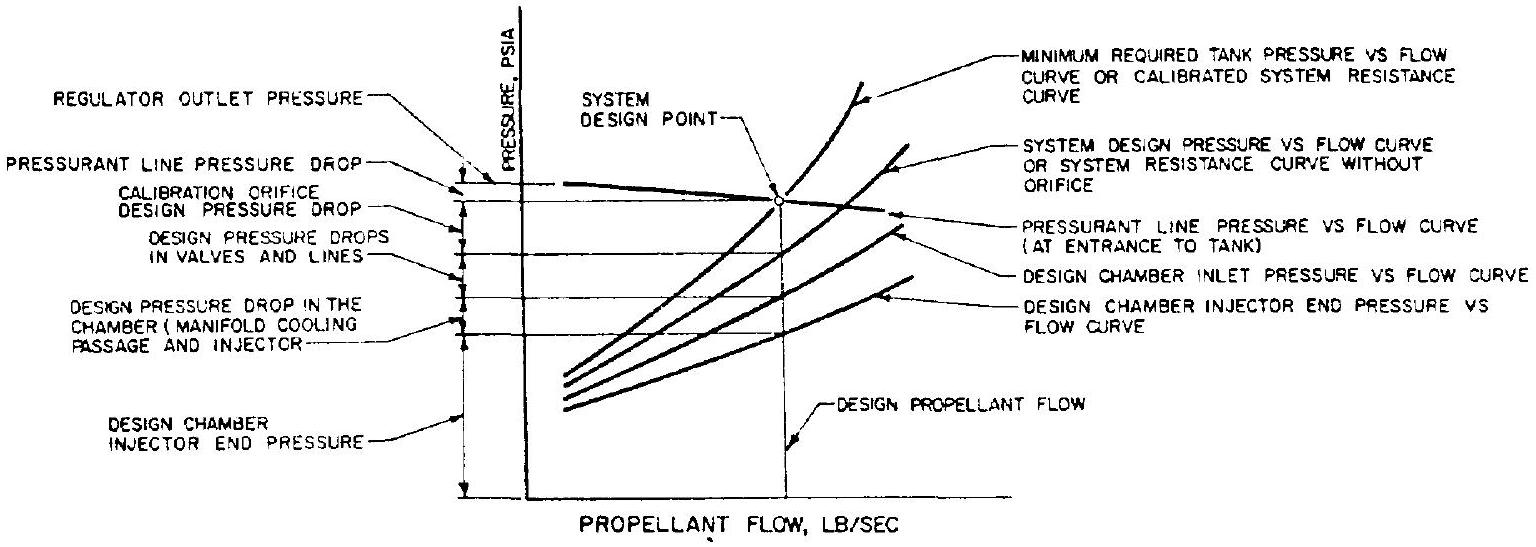 Figure 10-5.-Propellant flow design characteristics of a typical pressure feed engine system (oxidizer or fuel).
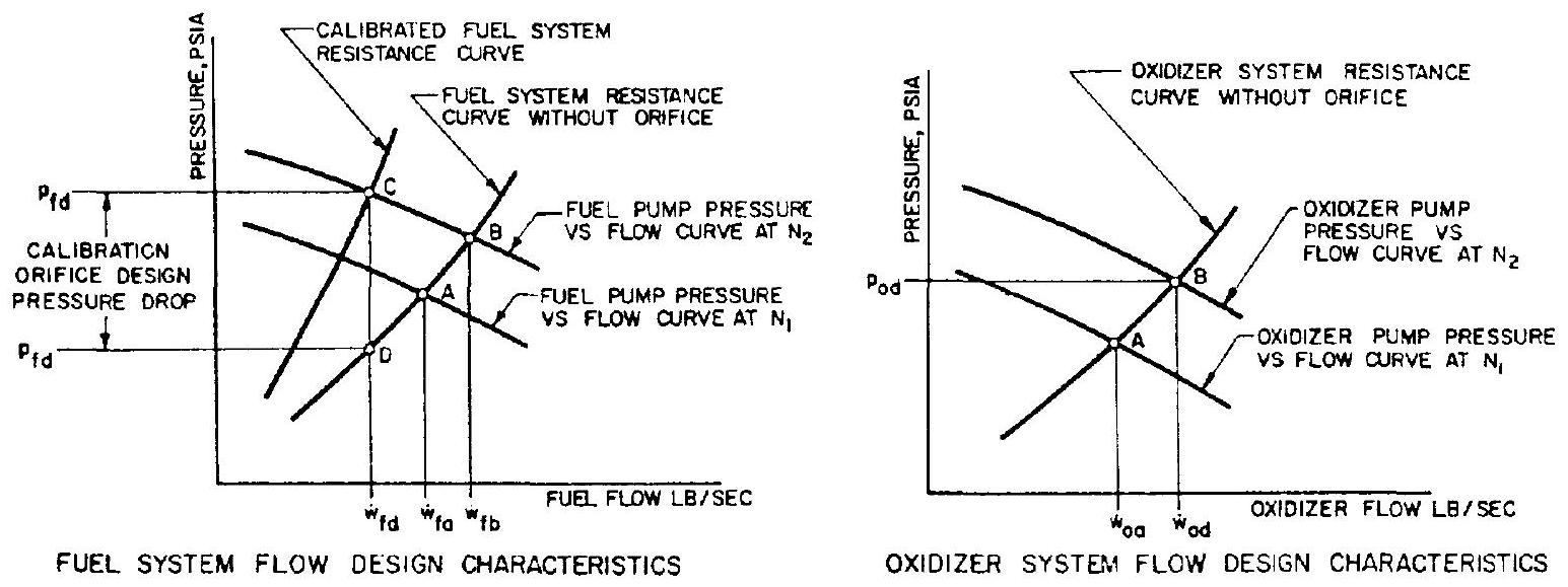 Figure 10-6.-Propellant flow design characteristics of the A-1 stage turbopump feed engine system.
of its flow characteristics from its design value will be kept within a reasonable limit, in order to facilitate systems calibration, and to keep other system components in their design operating region. (3) Sufficient pressure head should be set aside in each engine propellant feed system to compensate for contingencies due to component flow resistance deviations. The propellant feed system can then be calibrated by means of orifices or other adjusting means.
Design for Calibration of a Pressure Feed System
The first design step is the determination of the design flow rate of each propellant, as calculated from rated systems thrust, design mixture ratio, and (as verified by actual thrust chamber test firings). Based on these flow rates, the pressure drops of the various components at the design operating point can be estimated from previous design data, or as obtained from actual testing. Certain components may have to be newly designed for the specific design pressure drops allowed by the system.
The design pressure versus flow curve of either propellant flow system can be obtained by the summation of design chamber pressure versus flow and component design pressure drop characteristics, as shown in figure 10-5. In addition, an orifice is introduced in each propellant flow system for calibration. The minimum required tank pressure versus flow curve for each propellant is thus derived. In most pressure feed systems, the design orifice pressure drop for systems calibration determines the maximum allowable cumulative pressure drop increase of the components above their nominal values. A suitable tank pressurization system can then be designed, compatible with minimum required tank pressure versus flow characteristics.
Sample Calculation (10-1)
The following data are available from analyses and component tests for the A-4 stage propulsion system, at rated thrust conditions:
Thrust chamber injector end pressure range required to maintain rated thrust Thrust chamber injector pressure drop range (both oxidizer and fuel) Thrust chamber oxidizer dome pressure drop Oxidizer line pressure drop Main oxidizer valve pressure drop (at the fully open position) Thrust chamber fuel manifold pressure drop Fuel line pressure drop Main fuel valve pressure drop (at the fully open position) Pressure allowance required for mixture ratio control by oxidizer valve vernier positioning fig. Determine the design pressure drops of the calibration orifices, and the minimum required tank pressures for design flow rates.
Solution
The design pressure drop of a calibration orifice must be equal to the sum of the maximum pressure drop increases of components above their design values. Thus:
The design pressure drop of the oxidizer calibration orifice .
The minimum required oxidizer tank pressure at the design flow rate .
The design pressure drop of fuel calibration orifice .
The minimum required fuel tank pressure at the design flow rate psia.
Design for Calibration of a Turbopump Feed System
The propellant flow characteristics downstream of the pump discharges of a turbopump feed system are similar to those of a pressure feed system. However, the difference in turbopump pressure or head versus flow characteristics from those of a pressurized system dictates a somewhat different approach to systems calibration. For mechanically coupled turbopump feed systems, such as the A-1 stage engine, systems calibration generally involves adjustment of the turbopump speed as well as the installation of an orifice in one of the propellant lines. For turbopump feed systems with dual turbine drive, such as the A-2 stage engine, the calibration can be accomplished by adjusting the speeds of both turbopumps.
The design principles for the calibration of mechanically coupled turbopump feed engine systems are best illustrated by a typical example, as shown in figure 10-6. Here, the propellant system resistance curves without orifices (representing conditions downstream of the pump discharges) are constructed based on the designs and test results of the components for the A-1 stage engine system. Next, the discharge pressure versus flow curves of both pumps are constructed from test data obtained with the A-1 stage engine turbopump, operated at speed . These pump curves intersect the corresponding system resistance curves at point A . At this speed, fuel flow rate is above, and oxidizer flow rate is below the required design flow rates, and .
To achieve the design oxidizer pump flow , at a desired discharge pressure , the design operating speed of the turbopump assembly must be raised to a required level by increasing the turbine gas flow. However, at this speed, the fuel pump, which is mounted on the same shaft as the oxidizer pump, would be delivering a flow rate considerably above the required design flow rate (point B in fig. 10-6). To reduce the fuel flow to , a calibration orifice is placed in the fuel line. This amounts to increasing the fuel pump discharge pressure at constant speed to , where is reached at point C . The pressure drop across the calibrating orifice is represented by , where is the desired fuel pressure.
If fuel flow rate is below and oxidizer flow rate is above the required design flow rates, the calibrating process would be to speed up the turbopump to obtain the desired fuel flow, and to place an orifice in the oxidizer line. However, it is generally desirable to place the orifice in the system of the propellant with the higher boiling point. In this situation, therefore, and also when the pressure drop across a calibrating orifice tends to become excessive, it is customary to trim the pump impeller so as to reduce the effective speed, and thus attain the required flow and pressure levels. In view of pump efficiency effects, it is desirable to trim the pump drawing the smaller horsepower, usually the one with the lower mass flow rate, except in cases of extreme density differences. The adjustment of the turbine gas flow rate, and thus the turbopump operating speed, can also be made by means of orifices in the turbine inlet gas line, or in the gas generator propellant lines.
In general, turbopump feed systems afford less stringent requirements for the various components regarding deviations from their design steady-state flow values, because the system is inherently more flexible. However, systems dynamic characteristics under transient conditions may restrict these deviations.
Sample Calculation (10-2)
The following design values and allowable deviations are given for the A-1 stage LOX/RP-1 engine system components, at rated thrust:
Thrust chamber injector end pressure Thrust chamber injector pressure drop (both oxidizer and fuel) Thrust chamber oxidizer dome pressure drop Oxidizer line pressure drop Main oxidizer valve pressure drop Oxidizer pump specific speed, Oxidizer pump suction pressure Oxidizer pump discharge pressure at 7000 rpm and a design flow rate of Thrust chamber fuel jacket and manifold pressure drop Fuel line pressure drop Main fuel valve pressure drop Fuel pump specific speed, Fuel pump suction pressure Fuel pump discharge pressure at 7000 rpm and a design flow rate of psi
Determine the location of the calibration orifice, its nominal design pressure drop, and its expected range of adjustment.
Solution (see sample calculation (6-2))
The required oxidizer pressure head at the design point psia.
The required fuel pressure head at the design point .
Since the LOX pump discharge pressure is 1505 psia , but the fuel pump discharge pressure is 1720 psia , the calibration orifice must be located in the fuel system.
The nominal orifice design pressure drop .
From a detail analysis, we have found that the change of the fuel pump discharge pressure, as a function of turbopump speed increase or decrease, is a fraction of that of the oxidizer pump discharge pressure. Due to the effects of chamber pressure deviations, therefore, the maximum value of fuel calibration orifice pressure drop is required when the following conditions exist: (a) Thrust chamber injector end pressure is at its lower limit ( 1065 psia ) (b) All pressure drops in oxidizer passages are at their higher limits (c) All pressure drops in fuel passages are at their lower limits (d) Oxidizer pump discharge pressure is 25 psi below its nominal value at the turbopump speed commensurate with the stated specific speed (e) Fuel pump discharge pressure is 25 psi above its nominal value, at the same speed The equivalent required oxidizer pump discharge pressure under these conditions .
Required oxidizer pump developed head
Oxidizer pump volumetric flow rate
Substitute this into equation (6-7) to obtain the required pump speed
Fuel pump volumetric flow
From equation (6-7), the fuel pump nominal developed head at 7190 rpm
or
The equivalent fuel pump discharge pressure under these conditions would be .
The required pressure drop for the fuel line calibration orifice thus would be 1785-1065-180 .
Similarly, a minimum fuel calibration orifice pressure drop is required when the following conditions exist: (a) Thrust chamber injector end pressure is at its higher limit ( 1125 psia ), and conditions (b), (c), (d), and (e) above are reversed The equivalent required oxidizer pump discharge pressure under these conditions psia.
Required oxidizer pump developed head
Substitute this into equation (6-7); the required pump speed
From equation (6-7), the fuel pump nominal developed head
or
The equivalent fuel pump discharge pressure under these conditions would be .
The required pressure drop of fuel line calibration orifice under these conditions would be .
Therefore the required range of adjustment for the pressure drop of the fuel line calibration orifice is from 2 to 216 psi .