10.9 ENGINE-TO-VEHICLE INTERFACE
Throughout this book, references have been made to the ultimate purpose of rocket engine design and production: propulsion of a vehicle. Some of the principal engine-to-vehicle interfaces, such as thrust mount, and pneumatic, fluid, electrical and propellant lines, have been discussed in preceding chapters. In this section, we will summarize a number of vital engine-tovehicle interfaces, of which the engine designer should also be cognizant.
Design Documentation
Adequate mechanical design data, vital for the physical integration of the engine into a vehicle system, must be properly documented by the engine systems designer. The following data are considered minimum requirements: (1) Engine system general arrangement draw-ing.-This drawing defines the engine space envelope and the locations and detail of various agreed-upon vehicle connect points, such as Thrust or gimbal mount Gimbal actuator attach points Fuel and oxidizer inlet flanges Hydraulic and pneumatic system connections Electrical and instrumentation connections (2) Mechanical dimensions, tolerances, seals (if any), fasteners, and loads at the vehicle connect points listed (3) Engine system mass properties, as are shown in figure 2-6, which include engine weights, gimbaled mass, center of gravity, and moment of inertia for the basic engine, including accessories (4) Engine performance data (as in fig. 3-1) (5) Engine functional description (as in ch. III) (6) Engine handling procedures and equipment, needed for installation and maintenance (7) Engine servicing needs
As a rule, this information is compiled in detailed handbooks, which will accompany the engines when delivered to the vehicle contractor. However, several years before the engines are delivered and handbooks become available, the vehicle builder is in need of numerous engine design details in support of his stage design. An excellent source for this information is an "Engine Design Manual." It should be started during engine initial design and should be augmented as the design and, at a later date, the development progresses. Necessary revisions must be disseminated promptly.
Equally important is the early generation of an Interface Control Document. This defines each interface, for both mating sides, on one drawing.
Space Envelope
When installing an engine in a vehicle, it is not only necessary that it can be properly bolted to the vehicle thrust mount, but it is equally important that no other vehicle parts interfere. Space in the vehicle engine compartment must not only accommodate the engine envelope when in the neutral position, i.e., pointing straight aft, but when fully deflected in all directions as well. Typical maximum engine deflections range from to . For clusters, moreover, the possibility of faulty deflection of engines must be taken into account. Since space in the engine compartment of vehicles is usually limited, the need for the closest cooperation between engine and vehicle designer becomes apparent. This is especially true for upper stage clusters where large expansion area nozzles must be housed in minimum interstage structures.
Connect Panels
All engine-to-vehicle lines, which may amount to a dozen or more per eri ine, must be reliably connected for each engine installation, not only in the vehicle but in the static development and acceptance firing stands as well. It has been found beneficial to define this interface clearly by combining all lines in one or several terminal connecting panels (fig. 10-32). These panels, uniformly designed for all test locations, may be mounted on the vehicle (or test stand), or on the engine. For certain installations it may be advantageous to have matching panels on both: vehicle (or stand) and engine. Alined a short distance apart, standardized jumper lines between pairs of panels will permit rapid and reliable connections. A possible disadvantage of
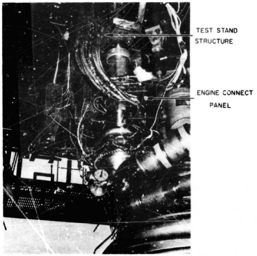 Figure 10-32.-Typical line connections on an experimental liquid rocket engine.
the panel method is that routing a line through the panels may result in additional line length, as compared to individual routing of each line. Through careful design and close coordination between engine and vehicle builder, considering optimum location, subdivision and orientation of the panels, advantages will, in most cases, far outweigh disadvantages.
Dynamic Interactions
The close coupling between propellant feed system, propulsion system, and vehicle structure may lead to underired interactions. These have manifested themselves as longitudinal vehicle oscillations (also referred to as "Pogo Stick Effect," "Accordion Motion," or "Spring-Mass Effect") at frequencies from approximately 10 to 20 cps . They have led, in at least one instance, to hicle destruction. The relationship of the contributing parameters is illustrated in figure 10-33 for a typical single-engine vehicle. The analyses and correction of these oscillations are extremely complex, particularly since they cannot be reliably reproduced during captive firings. It is believed, however, that any one of the coatributing factors can modulate thrust at a frequency at which the vehicle is resonant at certain tank levels (flight time, fig. 10-34). Through
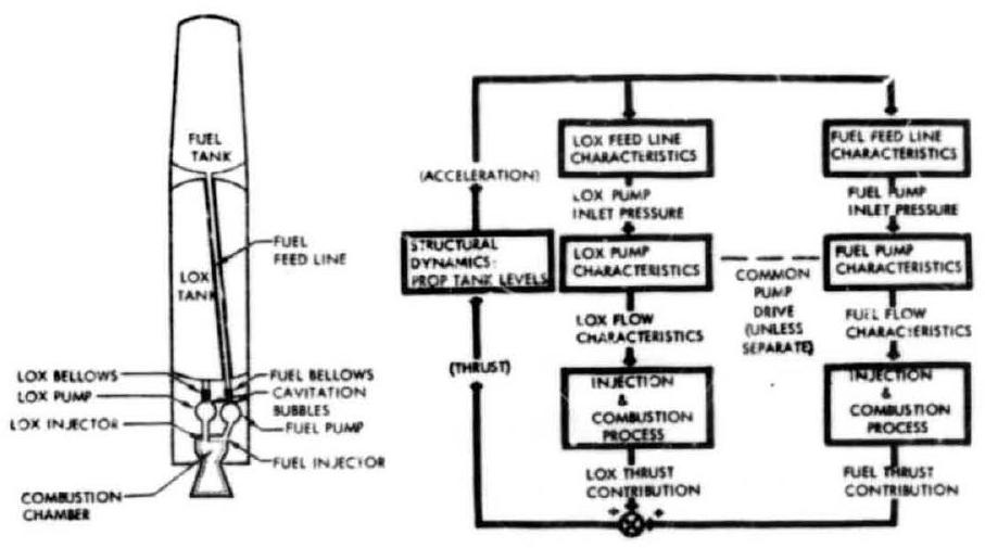 Figure 10-33.-Closed-loop coupling of propulsion system parameters and longitudinal vehicle mode.
acceleration, as a function of thrust, a powerful feedback exists. It has been demonstrated that the system can be detuned or uncoupled, through maripulation of propellant duct volumes, stiffening of structural members, and by other means. It is difficult if not impossible for the engine designer to predict analytically and prevent this problem, particularly since the vehicle configuration may not yet be firm. He may be called upon later for changes, however, if the problem shows up during flight.
Malfunction Reaction Systems
In chapter II we have discussed reliability and failure modes, as well as certain preventive measures. In the framework of engine-to-vehicle interfaces, some additional detail follows.
Engine Failure Sensing and Shutoff System (EFSS)
These systems have been in use since the early beginnings of liquid rocket engine application. They are specially important during engine
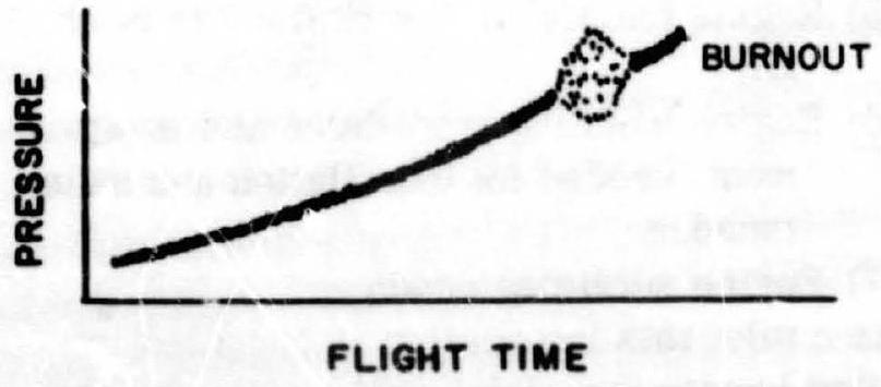 Figure 10-34.-Typical pump inlet pressure variation of a vehicle affected by longitudina! oscillations.
and early cluster development. Part of it may later become a portion of flight emergency detection systems (EDS) and engine-out systems (see ch. II). The following list of major engineoriented malfunctions, which is not necessarily complete, should be considered:
Pump inlet pressures below safe minimum Turbopump overspeed Turbopump bearing overheating Excessive turbopump leaks Turbine gas overtemperature Combustion instability Abnormal injection pressures Ignition failure Premature propellant depletion Electrical power failure Pneumatic pressure failure Improper valve positions Fires
Because of their potential sudden destructive effects, many of the malfunctions will be sensed and the signals used to initiate immediate automatic cutoff. For others which would not create an emergency within, say, fractions of a second, it is not uncommon to simply mark their allowable minimum and/or maximum values on an inking recorder chart which is watched by an observer during test. If the recorder needle goes outside of the marked margin, the observer initiates cutoff manually.
For flight, a few selected highly critical parameters of the EFSS may be retained for automatic engine cutoff or mission abortion. In this case, if the engine failure sensing and shutoff system were called upon to shut down an engine, and the flight is continued with the remaining engines, a vehicle-mounted electronic logic must sense the shutdown and take certain actions. These may include:
Closure of emergency shutoff valves in the ducts to the defunct engine, but not those in the others. Disconnection of electric power to the defunct engine only. Resetting or disarming of backup cutoff timers, since the reduced number of engines will consume the available propellants over a longer period of time. Locking of the defunct engine in the neutral gimbal position.
Heat Protection
Rarely in our technology had lowest and highest temperatures to be handled so close together as in a liquid propellant rocket engine. Earlier we discussed the need for insulation, to maintain temperatures as low as in certain ducts, or for heaters to protect sensitive components against these temperatures. At the same time, in other areas at or around the engine, protection must be provided against the very high temperatures of the combustion process and the emerging gas jet, such as cooling of the thrust chamber. The exhaust jet, at sea level, usually is not a major problem, unless blowback occurs from the flame deflector. At higher altitudes with vacuum or near-vacuum pressures, however, which are experienced even by first stages for the last portion of their flight, a substantial portion of the thrust chamber gas jet expands sideways from the nozzle exit, forming a plume, creating considerable backwash and radiating powerfully back into the engine compartment. This endangers both engine and vehicle components. Surface temperatures of or more may result unless heat protection is provided. In some cases it may be too cumbersome to provide individual insulation for each component. Also, excessive weight penalties may be incurred. A protective heat shield, forming a closeout diaphragm, may then be more effective (fig. 10-35). This shield may be supported from a stationary (center) engine, if available, or from a supporting structure.
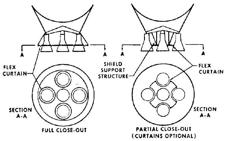 Figure 10-35.-Typical base heat protection concepts (center engine fixed, outer engines gimbaled).
Design and installation of the base heat shield requires closest cooperation between engine and vehicle designer. It must be determined, through special model tests, whether a partial or a full closeout is required. In most designs the shield connects to the engine nozzle. Suitable brackets must therefore be provided. During gimbaling the heat shield will resist the engine motion. The forces encountered must be considered in the power budget for the hydraulic actuators. Here it must be taken into account that the heat shield flex curtains may be quite cold prior to engine start and still remain relatively cool at the far side, as planned, during stage operation.
In addition to backwash and radiation, which are generally not harmful to the internally cooled engine nozzle itself, mutual gas jet impingement between engines may occur from extreme deflection during gimbaling. Unless a major control malfunction occurred, this should affect the nozzle only for very brief periods near the exit. However, the heat may affect chamber structural elements, such as stiffening bands, which are not internally cooled. A heat-protective strip, a few inches wide, of ablative or other suitable material applied to the nozzle should suffice in most cases (fig. 10-36). Obviously, this type of protection is not required for single-engine vehicles.
Engine Prestart Conditioning and Start
Functional conditions required within the engine to assure its readiness to start have been discussed earlier. When installed in the vehicle, the engine also requires external conditions which must be met by the vehicle builder. Provided that prelaunch checkouts have ascertained readiness with regard to absence of leaks, correct valve positions, etc., prestart conditioning of the engine essentially refers to temperature and pressure levels around the engine and at the pump inlets. For both, early cooperation between engine and vehicle designer to arrive at a mutually feasible solution is essential. Without it, the optimistic note in engine drawings "to be supplied by vehicle contractor" will accomplish little.
Certain engine subsystems, such as hydraulic components, control systems, and valve actua-
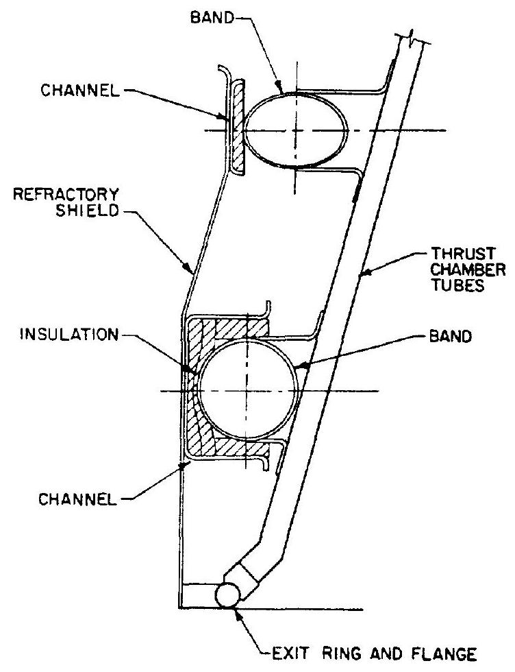 Figure 10-36.-Center-engine flame impingement shield.
tion mechanisms, can function properly only if they are within a specified temperature range. Engine systems not employing cryogenic propellants may be dependent on heating or cooling only if prolonged coasting times in space are involved. Engine systems which do use cryogenic propellants almost always need at least some heating. The cryogenic propellants within the engine following start of tanking, and the heat absorption of tank surfaces and lines may rapidly lower the air temperature surrounding the engine to several hundred degrees below .
Since most vehicle systems will specify an allowable hold period following tanking to allow for adjustments, checkout of other systems, to wait for optimum launch times (rendezvous missions), etc., severe subcooling of engine components may occur.
The temperature environment can be substantially improved by the vehicle builder through engine compartment purges with warm gases (fig. 10-37). If an inert gas is used, this has the
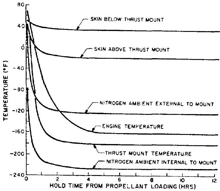 Figure 10-37.-Typical interstage temperature environment for an upper space vehicle stage using cryogenic propellants. 565 SCFM, nitrogen purge.
additional advantage of counteracting the accumulation of combustible gas mixtures from minor leaks. However, the vehicle builder's possibilities of heating through use of compartment gas purges are definitely limited. Some of the limitations stem from the engine designer's own specifications, which require avoidance of elevated temperatures around components containing cryogenic fluids to minimize boiloff and to prevent formation of gas bubbles. Also, certain structural members must be kept below maximum temperatures because of their strength characteristics. Another limitation is established by the purge gas requirements and necessary heating provisions which would become prohibitive if it were attempted to raise compartment temperatures to above or even to . Figure 10-38 shows the effects of increased purge flow and temperatures over those of figure 10-37. The analyses on which the graphs are based have shown that a further increase of the purge rate to 12000 SCFM (standard cubic feet per minute) and barely raises the interstage temperature above .
At the same time the propellant boiloff rates in exposed ducts increased tenfold over those under conditions of figure 10-37. The locations quoted are identified in figure 10-39.
For most applications the purges to the various areas are supplied from a ground source. Once preconditioned, affected components can
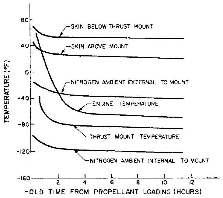 Figure 10-38.-Typical interstage environment for an upper space vehicle stage using cryogenic propellants. nitrogen purge.
be expected to maintain their temperature within an allowable band after vehicle liftoff during the relatively short boost periods. Only stages with prolonged cruising times may require an onboard purge supply system which imposes payload penalties.
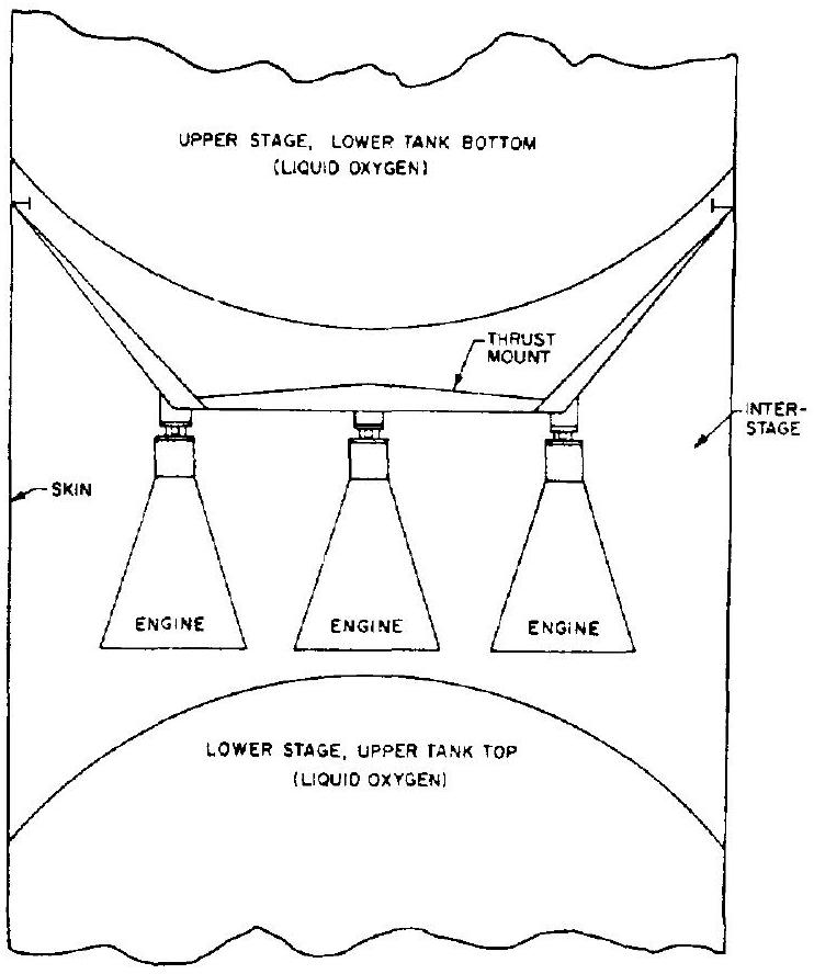 Figure 10-39.-Multistage vehicle interstage.
Literally a few inches away from the components requiring protection against low temperatures are others which must be protected against warmup due to influx of heat. Here again noncryogenic propellants pose few problems. By contrast, cryogenic systems, in particular those including liquid hydrogen, are very sensitive to heat influx. The effects on pump NPSH, which includes the vapor pressure of the fluid pumped, were discussed in detail in section 8.5 in connection with tank insulation. For engine start, which involves the cryogenic fluids stored in the ducts immediately upstream of the engine and within the engine itself, insulation may become prohibitively complex. Continuous removal of superheated cryogenic fluids from the engine system and substitution of fresh liquid, therefore, has been widely used. This can be accomplished through continuous overboard bleeding or through recirculation back to the tank. In both cases, the liquids are tapped off at a point farthest away from the pump inlets and routed to the stage for overboard dumping or return to the tanks. A small auxiliary pump is often required to obtain the minimum flow rates required for adequate bleeding.
During engine development, and even during vehicle static firing programs, relatively favorable prestart conditions exist: the enclosing interstage is not in place, hold periods are under better control, cold lower stage tank surfaces are absent. There is thus the danger that what worked faultlessly under these conditions will fail in vehicle flight. A realistic recognition of this situation and close coordination between the two design teams in the early phases of engine and vehicle design and development is therefore vital.
For first-stage applications, the engine builder is relatively independent regarding start characteristics and sequence. The vehicle will not take off until thrust exceeds vehicle weight, gravity holds the propellants at the tank outlets, and all parameters are closely monitored from the ground control center. If a holddown period prior to vehicle release and takeoff is included, an additional safety margin exists.
For upper stage engine start, conditions become considerably more complicated. Absence of the propellant-settling effects of gravitation, the surrounding vacuum, altitude temperature conditions, and remoteness from ground stations can only crudely be simulated in ground tests. Therefore, until first flights of a new vehicle have been accomplished, the engine in-flight start sequence, which is closely interwoven with the stage separation sequence, must be planned based largely on analytical work. Neither vehicle builder nor engine designer can do this without consideration of, and consultation with the other. The following principal relationships must be considered:
Starting of the upper stage engines while the lower stage is still at full-thrust level is difficult, mainly because of the problems of flame impingement and exhaust gas dissipation from the interstage. Therefore, engine start following stage separation is preferred. However, in this case propellant settling from acceleration effects of the lower stage is no longer assured. Auxiliary propellant settling (or "ullage") rockets (usually solid propellant type) are required instead during engine starts. These add weight and drag and reduce payload. The size of the weight penalty, in turn, depends on engine-start characteristics (thrust-buildup time). For engines with relatively protracted buildup times, advanced initiation (with respect to lower stage thrust decay and separation) of upper stage engine start may substantially reduce the penalties. A second lopped off the ullage rocket burning times may save hundreds of pounds of stage weight. The same amount of time added may not only reduce payload weight but pose serious control problems to the space vehicle which floats essentially "rudderless" after separation and prior to the start of its own engines. From the foregoing the need for thorough mutual understanding of this important vehicle-to-engine interface becomes apparent.
Vibration Environment
Even a normally or "smoothly" operating rocket engine generates a vibration pattern which is transmitted mechanically through the thrust mount, or acoustically through the ambient atmosphere, if present, to the vehicle structure. Neglect of these vibrations by the vehicle builder may lead to serious structural weakness or malfunction of vital control organs mounted to the vehicle structure. Means of reducing the normal engine vibrations are limited and hard to analyze.
Rather, it is important that the engine developer establish as accurately as he can the existing acoustic and vibration pattern and inform the vehicle designer of his findings. Since the tiedown firing measurements cannot reliably predict free-flight conditions, a serious handicap exists. However, through his thorough understanding of the potential problems, and through specification in cooperation with the vehicle designer of static test and flight measurements, the engine designer can materially assist in reducing the incidence of serious problems.
Nozzle Expansion Area Ratio
From his own analyses, the engine designer may have selected a nozzle expansion area ratio which appears to be an optimum compromise between engine weight, engine performance, engine size, and producibility. When analyzed in the larger framework of vehicle performance, the selection may turn out not to be optimum. In reviewing the various influences, we will disregard single-engine first stages which are least affected. For stages with engine clusters, in particular, upper stages, the following must be considered:
Gimbal Angle
Following determination of the maximum gimbal angle required for safe vehicle guidance, including consideration of actuation malfunctions, the nozzle exit diameter will determine the attachment point distances (mounting pattern) of the engines in a cluster.
Vehicle Diameter
When mounted for proper gimbal capability, the envelope of the engine cluster must be in proper relationship to the vehicle diameter. If the cluster envelope is too large, the increase in vehicle dimensions may void all gains from a larger expansion area ratio. If engines are not permitted to protrude beyond the projected vehicle plane in neutral and/or in gimbaled position, an even more stringent situation exists.
Interstage Length
When mounted to the lower stage, the length of the upper stage engines will determine the length of the required interstage. For a vehicle of the Saturn V class, each additional inch of interstage length will cost approximately 40 pounds. Thus, here too, the added interstage weight required to accommodate a longer, better performing nozzle may void the theoretical gains.
Stage Separation
When separating the stages of a space vehicle, three basic possibilities exist:
- Leaving the interstage with the lower stage.-This requires the engines to pull out of the interstage cylinder during separation (fig. 10-40). If the clearance between engine skirts and interstage wall is marginal, complicated means may be required to avoid collisions between the separating stages. These may include a control system to tuck the engines inward, and then swing them out upon separation and start them. Any such system adds complexity, lowers reliability, and may add weight. A shorter nozzle skirt, of lesser diameter although somewhat lesser performance, may be better overall.
- Leaving the interstage with the upper stage.-To avoid the problem of stage collisions, it may appear attractive to leave the interstage attached to the upper stage. However, this adds inert weight to the upper stage. This penalty may be considerably larger than the performance loss from a somewhat shorter nozzle. Also, a control problem may be incurred in that the engine nozzles, in their outward gimbal deflection, still must clear the interstage wall. In joint optimization studies between engine and vehicle designer, the possibility of leaving part of the interstage with either stage may be considered.
- Leaving the interstage with the upper stage but dropping it in a second separation maneuver several seconds after first separation.-In this dual-separation sequence, the second separation may consist of shedding the interstage as a complete ring, possibly in combination with guide rails, or of blowing it off to the side in segments. For either method, some form of actuation is required in addition to accurate timing. Also, while the interstage is still attached, a serious base-heating problem may develop. The means required to overcome any difficulties with this separation method again may increase complexity and reduce reliability and partially neutralize nozzle performance gains.
Whichever method is applied, the thrust-decay characteristics of the spent lower stage engines
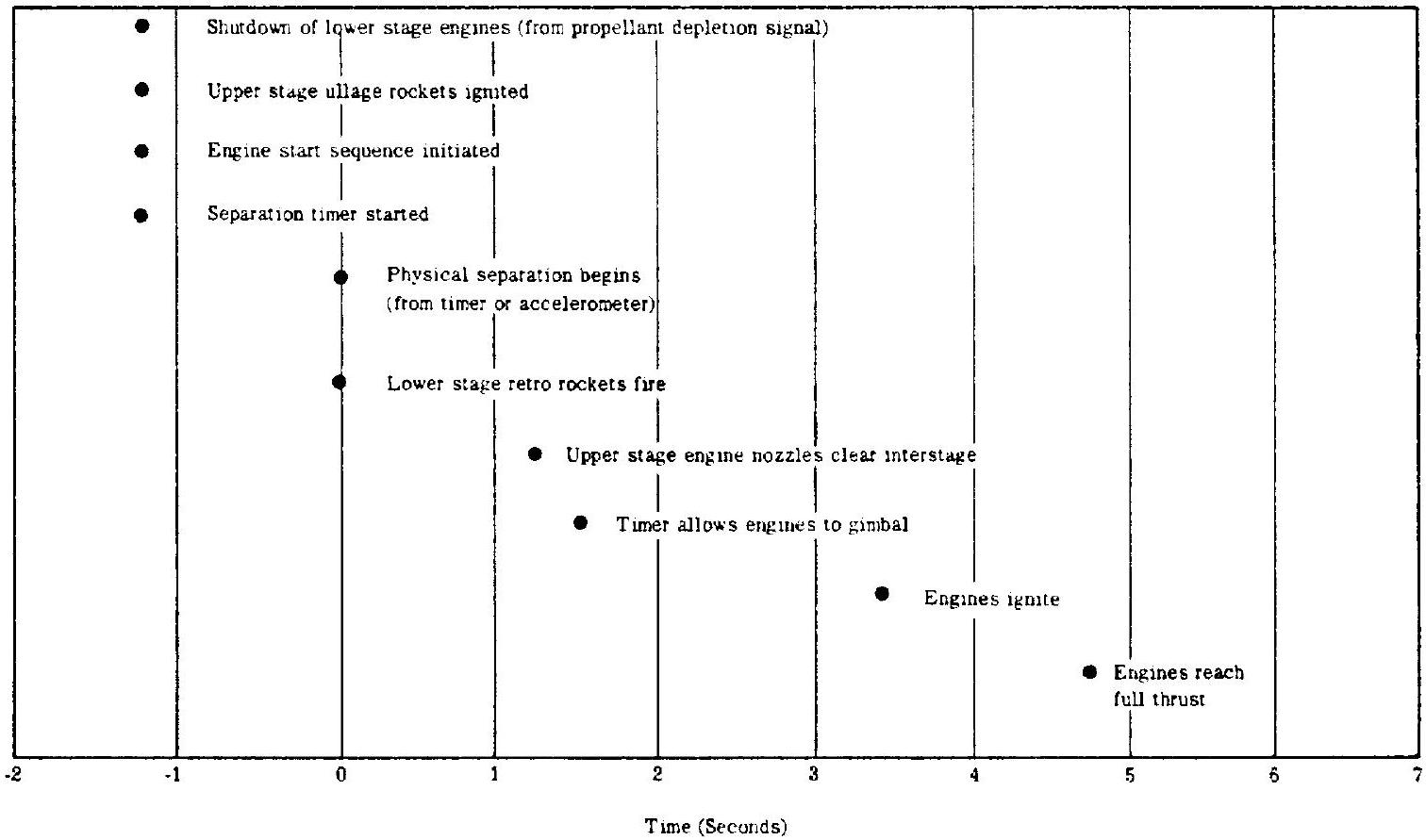 Figure 10-40.-Typical stage-separation sequence.
greatly affect the separation sequence and the clearances. To optimize these, the vehicle builder needs from the engine designer accurate information on thrust-decay characteristics and tolerances. This may be in the form of a graph, as shown in figure 10-41.
Flame Deflector Size
Although this is not entirely an engine-tovehicle interface, it is pointed out that enginenozzle size and arrangement on the vehicle, together with maximum gimbal angles, strongly influence the design of required flame deflectors on engine and stage static firing test stands, and of launcher flame deflectors. Here the problem is not so much one of optimizing vehicle performance, but of minimizing cost and of assuring the adequacy of these indispensable development tools.
Engine Handling, Installation, and Servicing Fixtures
For handling engine parts and assemblies during engine installation into development test stands and for various servicing functions, the engine builder requires numerous fixtures commonly referred to as engine GSE (ground support equipment). Some of these fixtures can be used by the vehicle contractor as designed, others could be used if only a few minor changes or additions were made. The funding required for GSE in a typical vehicle program is substantial and approximates that of the flight hardware. Common use of as many of these fixtures as possible by engine and vehicle builders is strongly advised. To assure this the two must work together from the earliest design inceptions.
Standardization
The task of mating engine and vehicle will be substantially facilitated if the designers of both work to the same standards. This applies to national standards, Government standards, company standards, to terminology, mathematical symbols, and to the measuring system (metric or English, decimals or fractions, tolerances). Since several avenues are open, it is necessary, at the very outset, to agree on which one shall be pursued. This requires close cooperation and full documentation.
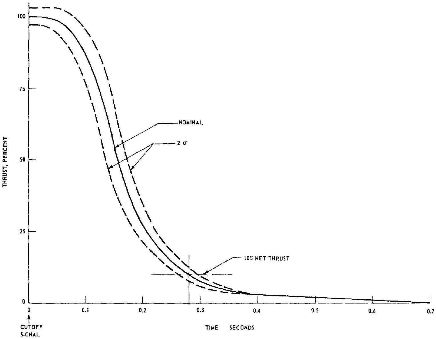 Figure 10-41.-Typical engine thrust decay deviations.
Delivery Schedules
For the vehicle builder to deliver his stage on time, complete and equipped with engines, the latter must be available to him with sufficient leadtime. If the engine builder is directly contracted by the vehicle contractor, this can be negotiated and followed up in a straightforward manner. In most cases, however, particularly with large liquid engines, these will be supplied to the vehicle contractor as Government-furnished equipment (GFE). The engine supplier, therefore, may not necessarily be fully cognizant of the detail vehicle needs. In either case, the engine designer and developer, to avoid sudden unexpected compression of his schedules, must make sure that his schedules for design, drawing release, manufacture, development, and engine delivery are in accord with the vehicle needs.
Maintenance and Logistics
Until reliable and economic methods are developed to recover and refurbish rocket vehicles, rocket engines will be used only once in flight, which will be preceded by a reasonable number of checkout and acceptance firings. The engine model specification will include the total prescribed run capability (lifetime) of the engine, usually expressed in multiples of the rated flight duration. A factor of, for instance, 6 , which includes a reserve for repetition of checkout runs, is typical. Because of the stringent weight considerations in rocket vehicles, engine design attempts to assure this life expectancy, but no more. Although reasonable safety factors make it most unlikely that the engine would completely collapse shortly after the allowable maximum run time is exceeded, the statistical probability of some engine part failing does increase. For this reason most engine specifications prescribe overhauls of a stated scope whenever this limit is exceeded.
Similarly, upper limits are set for storage times. If these are exceeded, routine replacement of certain engine parts will be made, notably of gaskets and seals. Rocket engine preservation and packaging methods are well developed, permitting storage periods from 3 to 5 years without overhaul.
During shipping, handling, installation, servicing, checkout, static firing, and launch preparation, damage of various types may be incurred by the engine because of parts failures, mishandling, oversights, or accidents. All incidents must be corrected by repair and/or parts replacements.
Any or all of the described maintenance action may be required while the engine is still with the engine builder, or following its delivery to the vehicle contractor. An accurate and effective maintenance or logistics plan must be worked out between the two contractors, or with their contracting agency, considering all handling needs at all test stations. This includes consideration of under what conditions engine return to the factory for overhauls, repairs, and parts replacements should be made. If return is not required, the correct handling fixtures and tools must be provided for each location. Above all, an adequate stock of spare parts must be planned. The engine designer will frequently be consulted for his advice in an effort to avoid both time losses due to lack of parts and costly overstocking.
Multiple-Engine Use
In view of the cost of rocket engine design, development, and procurement, common usage of a given engine for several vehicles, or for several stages of the same vehicle, is very desirable. Also logistics, handling, checkout, launch preparation, and instrumentation requirements can be substantially reduced or simplified. Caution must be exercised however, not to go "overboard," lest engine-to-vehicle interfaces become considerably more complicated.
Effort should be concentrated on the common usage of the major cost items and engine build- ing blocks, such as turbopumps, injectors, combustion chambers, gas generators, valves, gimbal blocks, and high-pressure ducts. Peripheral equipment, such as instrumentation lines, servicing lines, inlet ducts, and wire connections, should be left flexible enough to adapt them to each vehicle without compromise. It is tempting to procuring agencies to warehouse just one engine model and ship "from the shelf" to wherever the need arises. This convenience, however, may cost substantially more than the expected savings: In mission compromises, reduced reliability, increased coordination effort between engine builder and vehicle builders, substantially increased possibility of oversights and communication gaps, and cost- and time-consuming retrofits. As always, a joint thorough and unbiased analysis considering all aspects, including that of the long-range future, will readily yield information about the point of diminishing returns.
Reserves and Safety Margins
In his negotiations with the engine user, i.e., "the customer," which quite likely is a Government agency, the engine designer, like the vehicle builder, will frequently find himself under pressure to compromise. This may be to cut weight, to accelerate schedules, or to maintain reliability with dwindling funds. It is then that he will be most in need of his top management's understanding and support. But it is here also where he will be most criticized if it is found that his analyses were incomplete, superficial, not optimized, or heavily biased by safety factor upon safety factor. To strike an optimum balance between high performance and adequate safety factors and reserves is one of the finest arts of engineering and is directly translatable into the degree of success. Once the designer is certain that he has achieved this balance, or if he is concerned that he may lose it, he should so go on record. If he does, he should also remember Edmund Berkeley's observation: "Thoughtful and tolerant disagreement is the finest climate for scientific progress."
[^12]
Chapter XI
Design of Liquid Propellant Space Engines
Liquid propellant space engines embody the same operating principles and general characteristics as the liquid propellant rocket systems previously discussed. However, their specific missions for the use in spacecraft require special design considerations, which will now be discussed.