8.6 DESIGN OF FIBER-GLASS FILAMENTWOUND LIQUID PROPELLANT TANKS
Most of the pressure vessels which possess surfaces of revolution can be fabricated conveniently by the technique of filament winding. By this method a lightweight structural member can be produced with mechanical precision and versatility of construction and materials. A strength-to-density ratio, , can be obtained by filament winding and impregnating the fiber-glass roving with a suitable resin, which is higher than can be achieved by any other method or material. For instance, the strength-to-density ratio of a fiber-glass filament-would resin-bonded structure (average ) is about twice that of high-strength alloy steels.
Good reliability and close dimensional control of filament-wound pressure vessels is assured through the use of calibrated winding machines which orient the reinforcing fibers precisely. However, most of the liquid propellants are not compatible with resin-impregnated, fiber-glass structures. Therefore, an aluminum tank liner which is compatible with both propellants, must be used to separate the fiber glass from the liquid. It also provides a positive sealing barrier, since the resin-bonded fiber-glass material is pervious to both liquid and vapor over extended periods. Figure 8-15 presents a typical aluminumlined, fiber-glass filament-wound liquid propellant tank.
Design and fabrication of fiber-glass filamentwound tanks with a thin aluminum liner is basically simple. However, a key problem arises from the fact that the modulus of elasticity of fiber-glass resin-bonded materials is about psi , while that of aluminum is about , and that the strength of the aluminum is usually no more than a third of that of the fiber glass. Since the geometry of the tanks usually imposes equal strain on aluminum liner and fiber glass as the tank is pressurized, the aluminum becomes loaded to its elastic limit long before the fiber glass reaches the level of its high-strength capability. Consequently, with a plain liner configuration, the aluminum is stretched far beyond its elastic limit and forced back to its original shape each time the tank is pressure cycled. Thus, the liner may experience fatigue failure after a small number of pressure cycles. The pressure-cycle life of a plain liner depends on amount of stretch beyond the elastic limit, type of aluminum, bonding between lines and fiber glass, weld joints, variation in thickness and contours, etc. A welldesigned, plain-type tank liner should have a life of about 10 to 20 pressure cycles.
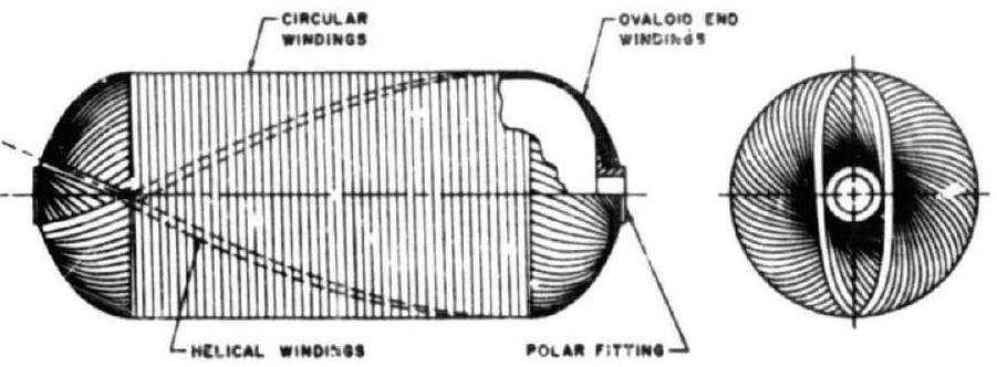 Figure 8-15.-A typical aluminum-lined, fiberglass, filament-wound liquid propellant tank.
C'ne design approach to extend cycle life is to use a corrugated liner. The corrugations have an effect equivalent to reducing the modulus of elasticity of the aluminum liner to value less than that of the fiber glass. For instance, if the fiber glass is stressed to 100000 psi and has a modulus of elasticity of , its extension will be 2 percent. The corrugations of the liner then should be designed to permit the 2-percent extension so that the aluminum will not be stressed beyond its elastic limit.