8.5 DESIGN OF CRYOGENIC LIQUID PROPELLANT TANKS AND THEIR INSULATION
In the design of cryogenic propellant tanks, there are several potential problem areas which may affect proper functioning and reliability: (1) Properties of the tank construction materials at the cryogenic propellant service temperature range (2) Thermal stresses induced in the tank structure by temperature gradients (3) The relief of tank pressure caused by boiloff of the cryogenic propellants (4) Thermal insulation of the tank walls
The knowledge of the precise strength characteristics, degree of brittleness, and notch sensitivity of the tank construction materials at cryogenic temperatures (as low as for liquid hydrogen service) is a prerequisite for their selection. In general, most of the aluminum alloys, the austenitic and semiaustenitic stainless steels, possess good mechanical properties at cryogenic temperatures (also see ch. II). The thermal stresses can be analyzed by determining the temperature profile at various regions of the tank and may be minimized by discrete design approaches. The capacity of the tank relief valve should be based on the maximum anticipated propellant boiloff rate during ground hold and actual operation of the vehicle systems.
Among the cryogenic propellants, liquid hydrogen imposes the most serious tank design problems. This is mainly due to its very low service temperature and its relatively large specific volume. Design problems are especially acute with the hydrogen tank insulation. It often becomes one of the most critical design factors in a hydrogen-fueled vehicle system. The difficulties arising in hydrogen systems in connection with heat transfer may be dramatically illustrated as follows:
Assume two tanks of equal size, subject to the same heat influx per unit time. One is filled with liquid oxygen, the other with liquid hydrogen. The ratio of heat of vaporization per unit weight , but the density ratio is . Thus the volume rate of vaporization in the hydrogen tank is 6.85 times faster than in oxygen. In reality, the heat influxes would not be equal for two uninsulated tanks, because of the higher temperature differential across the wall, and especially because of the greatly increased heat-transfer rate from air liquefaction on the hydrogen tank surface. This may further accelerate the hydrogen volume boiloff rate to approximately 70 times that of oxygen. In an actual oxygen/hydrogen system, operating at a weight mixture ratio , the tanked mixture ratio by volume is . Depending on the shape of the tanks (surface ratio), this may again double or triple the relative boiloff rate of hydrogen. The absolute necessity for insulation to drastically reduce heat influx into a hydrogen system becomes apparent.
Boiloff rates are not the only problem caused by the physical properties of hydrogen. Near the ambient boiling temperature, the gradient of vapor pressure is , as compared to for liquid oxygen. Moreover, this gradient increases rapidly with increasing temperature, which would be experienced following tank pressurization. Figures and show the trend for both liquid oxygen and hydrogen. The data have great significance to pump NPSH. As may be seen, just one degree of liquid-hydrogen-temperature rise requires a psi increase in tank pressure to maintain proper NPSH. In a large vehicle, the required increase in tankwall thickness may affect payload capability noticeably. The situation is further aggravated by the high heat influx into hydrogen, for reasons mentioned in connection with boiloff. Even for relatively short boost periods, rapid warmup may create a problem more severe than boiloff, and places further emphasis on adequate insulation. The following discussion of tank insulations,
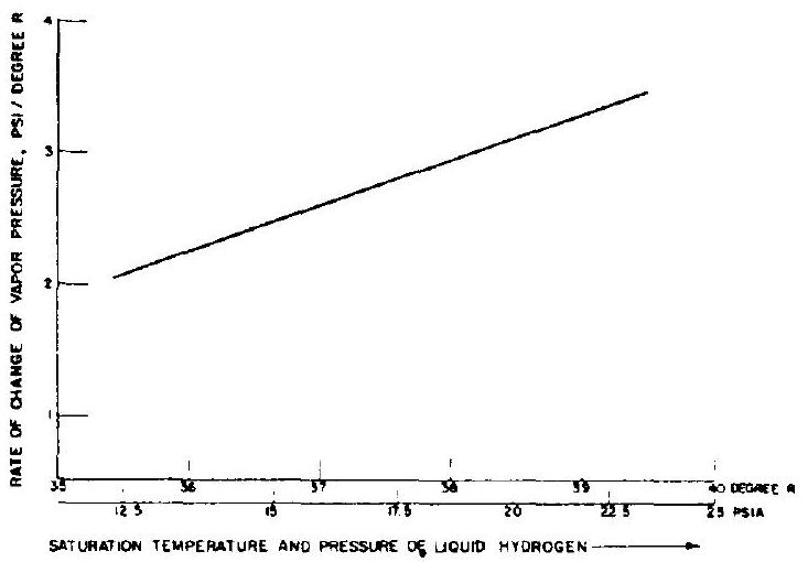 Figure 8-11.-Rate of change of saturation vapor pressure to temperature for liquid hydrogen.
therefore, is specially slanted to hydrogen service.
Insulation Requirements for the Cryogenic Propellant Tanks
Most vehicle missions include three distinct phases during which effective insulation for the cryogenic propellant tanks is essential: ground hold period, the boost phase, and coast flight in space. The propellant tank insulation design will primarily be based on flight performance criteria. However, propellant evaporative losses during long hold periods on the ground requiring continuous topping may also become a significant cost item. If long hold periods with a filled tank are anticipated, it may be indeed economical
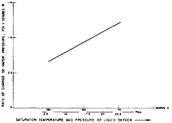 Figure 8-12.-Rate of change of saturation vapor pressure to temperature for liquid oxygen.
to provide an insulating blanket on the tanks, which is remotely removed just prior to liftoff. During the boost phase, high temperatures from aerodynamic heating, and large aerodynamic forces are encountered. Although of short duration, this phase dictates the structural elements of the insulation. During coast flight in space, the principal source of thermal energy is radiation from the Sun and the planets. By the use of radiation shields surrounding the basic tank insulation, the heat flux across the tank wall can be effectively controlled. The properties of the materials used in a solar shield are very important, such as the absorptivity and emissivity of the surface when subjected to various types of radiation and body temperatures. Magnesium oxide and silver are two materials showing promise for use in solar shields. These materials may be applied as coatings onto a lighter base material such as aluminum. The amount of shielding required depends on the duration of the coast flight and on optimization of shield weight versus propellant boiloff weight.
Basic Insulation Types
Major desirable design features of an insulation include: light weight, uniform and repeatable insulation characteristics, ease of application, low cost, low hazard, reasonable ruggedness, ease of repair, good reliability, and above all, low heat conductivity.
Excellent results can be achieved with a laminated-type insulation. This employs an aluminum foil and fiber-glass structure, often in multiple layers. The aluminum foils act as reflectors, effectively rejecting radiative heat, while the evacuated space in between prevents conductive heat transfer. This insulation can be applied to single-curved and to large-diameter, double-curved surfaces. The laminar insulation is sensitive to damage, however, possibly resulting in loss of vacuum due to cracks and to infiltration of leak gases. Application to airborne system thus has been infrequent.
For the latter, honeycomb-supported structures are finding wide application. Figure 8-13 shows the typical example of an externally applied hydrogen tank insulation of this type. A - to -inch nominal-size plastic honeycomb is installed between an inner and outer facing
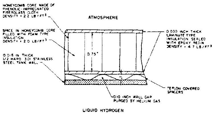 Figure 8-13.-Construction elements of a typical liquid hydrogen tank insulation design (external type).
sheet. The cells may or may not (weight!) be filled with an isocyanate-type foam. The foam bubbles or the properly sealed cells will form individual vacuum spaces when cold (cryopumping). However, because of the possibility of vacuum degradation by infiltration of air (outer insulation), or hydrogen (inside insulation), it is often preferred to purge the cells with helium, for which lateral passage ways must be provided. The purge also serves as a leak-detection device, in conjunction with gas analyzers, to detect contamination of the helium from leaks. In figure 8-13, a separate gap is purged with helium, rather than the honeycomb cells.
The thermal conductivity of the insulation shown is about ).
Thermal conductivities of various types of insulation vary from to Btu-in . Their densities range from 2.0 to . Since the quality of an insulation will affect cost and weight, an optimization study will have to be made, based on mission characteristics.
Sample Calculation (8-6)
Determine the heat-transfer rates in sec across the tank insulation shown in figure 8-13 during- (a) Ground hold.-The temperature of the insulation surface near the tank wall is around and the outer surface is . (b) Boost phase.-The inner insulation surface temperature reaches and the outer insulation temperature reaches .
Solution
(a) During ground hold, the temperature differential across the insulation . The overall thickness of the insulation . From equation (4-19), the heat transfer rate
(b) During the boost phase, . The heat-transfer rate
Selection of Tank Insulation Designs
Many factors will influence the selection of a tank insulation design. The insulation may be located internal or external to the tank wall; it can be integral, or disposable during boost; i.e., it can be bonded in place or mechanically retained. Basically, any insulation applied to a tank must be justified with respect to advantages of performance and/or economy.
Locating the insulation inside of the propellant tank has the obvious advantage of protecting the insulation from handling damage. The tank structure is isolated from the severest lowtemperature effects of the propellant and is thus subjected to only moderate thermal cycling from its source. Internal insulation also minimizes propellant loss when chilling the tank during filling. However, if a crack or leak should occur in internal insulation of a hydrogen tank, gaseous hydrogen would enter the crack and gradually increase the heat transfer. Other undesirable features of internal insulation are apparent, such as: difficulties in installation; in locating and repairing of leaks; and in cleaning the tank. Internal insulation is also subject to higher pressures and more severe temperature effects which tend to impair the insulation sealing.
External insulation has the advantage of isolating the tank structure from the extreme temperature of aerodynamic heating during boost. Installation, repair, and sealing of the external
 SECTION A-A
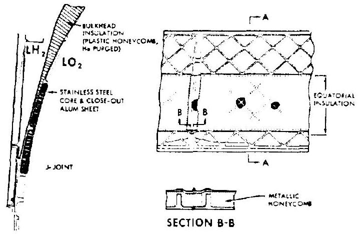
Figure 8-14.-Design of a typical insulated common bulkhead separating and tanks. insulation can all be done without special consideration of access, ventilation, and curing techniques in closed areas. However, special consideration will be required for tank leak detection, especially with integrally insulated areas. If a crack does occur in the external insulation, liquefaction of air and cryopumping will occur resulting in a significant rise in heat transfer.
Insulation for Common Bulkheads
When a common bulkhead is used between propellant tanks and cryogenics are involved, insulation is required to prevent freezing of the propellant with the higher boiling point. Figure 8-14 shows the equatorial area of a typical insulated common bulkhead. A fiber-glass honeycomb is located between a forward and an aft facing sheet. In the equatorial area, where the facing sheets have to be faired into the cylindrical tank portion, they are reinforced by waffle grid ribs. This design also requires special insulation on the inside of the LOX tank in the equatorial region. No foam filler was used in this particular example.