7.7 DESIGN OF DYNAMIC SEALS FOR FLUID-FLOW-CONTROL COMPONENTS
Apart from the static seals, which will be treated in chapter IX, two basic types of dynamic seals are required for fluid-flow-control components: seals for moving (reciprocating and rotating) cylindrical elements such as actuator pis- tons, shafts, and rods; and seals for valve seats. Here, too, temperature is one of the most important design considerations. Seals can be classified into those for medium-temperature service ( to ), low-temperature service ( to ), and high-temperature service ( and up). The selection of the configurations and the materials for these seals is based to a large extent on service conditions and type of fluid involved. Generally, soft nonmetallic or elastomeric seals are used wherever possible. The outstanding advantage of these seals is that they function satisfactorily despite minor imperfections in the seal or the mating part.
Design of Dynamic Seals for Medium-Temperature Services
Elastomeric O-rings have been widely applied as dynamic seals for moving cylindrical parts as well as for valve seats. However, proper design techniques must be observed to assure success. Figure 7-24 and table 7-5 represent recommended design practices for diametral-squeeze-type O-ring seals for typical dynamic and static applications. Figure 7-26 shows a typical O-ring seal used for a valve seat. Important design considerations for dynamic O-ring seals are summarized as follows:
- Design correlations between fluid pressure, O-ring compound hardness and diametral clearance.-A frequent cause of seal failure is the extrusion of diametral-squeeze-type O-rings into the clearance gap adjacent to the O-ring groove (when under pressure) (fig. 7-25), leaving a permanent deformation after the pressure is reduced. Fluid pressure influences O-ring seal design because it affects the choice of compound hardness. The combination of fluid pressure and chosen hardness will determine the maximum clearance that can be tolerated safely. A proper combination of clearance and O-ring hardness may prevent O -ring extrusion (table ). In general, the O-ring nominal section diameter is chosen as large as space and installation considerations will permit. Past designs usually will provide a useful guide. In addition, Teflon backup rings as shown in figure are recommended for dynamic O-ring seals at sealing pressures over 800 psi and for static O-ring seals at pressures above 1500 psi .
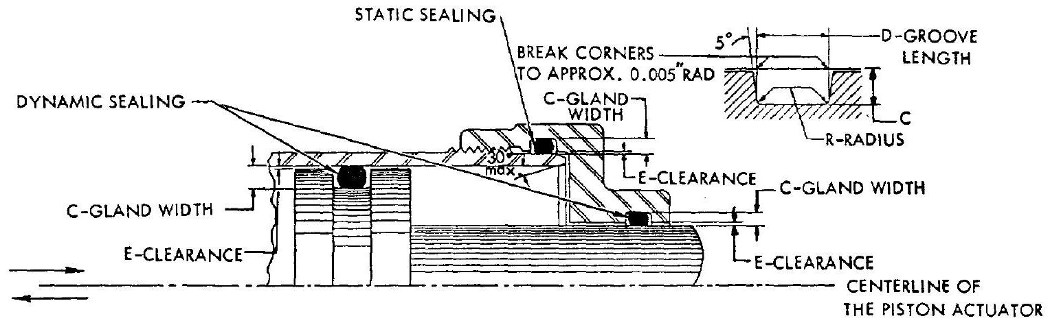 Figure 7-24.-Diametral-squeeze-type O-ring seals in typical dynamic and static applications.
- Surface finish requirements.-The finish of the sliding surfaces in contact with dynamic O-ring seals should be as smooth as possible. They should be ground, honed, or polished to a microinch finish of 8 to 10 rms . It has been found that a finish within this range yields a longer life than either rougher or smoother finishes. Codirectional patterns, as produced by honing, have been proven to be the best surface finish for any type of dynamic sliding seal. For still better results, after an initial finishing, the surface could be hard chrome or nickel plated and again finished. The plating provides a hard, slippery surface that resists corrosion, wear, and scratching. A microinch finish of 60 rms or bet- ter is recommended for surfaces in contact with static diametral-squeeze-type O-ring seals.
- Friction of dynamic O-ring seals.-The breakaway friction of a dynamic O-ring seal is usually about three times the running friction. Breakaway and running frictions increase with fluid pressure, O-ring hardness, diametral squeeze, and decrease of temperature. Accurate values of O-ring frictions can only be obtained experimentally for a given design.
- Selection of O-ring compounds.-A great variety of O-ring elastomer compounds is available, with trade names such as Silicone rubber, Buna N, Butyl, Viton, Teflon, and Kel-F. The selection of an O-ring compound and its physical [See fig. 7-15 for explanation of dimensions; all dimensions in inches]
Table 7-5.-Recommended Design Practice for Diametral-Squeeze-Type O-Ring Seals
| O-ring nominal section diameter | O-ring section diameter | Diametral squeeze, min | C-gland width | Dgroove length | Rradius, min | Ediametral clearance, max | ||
|---|---|---|---|---|---|---|---|---|
| Dynamic | Static | Dynamic | Static | |||||
| 1/16 | 0.010 | 0.015 | 0.057 | 0.052 | 3/32 | 1/64 | 0.005 | |
| 3/32 | . 010 | . 017 | . 090 | . 083 | 9/64 | 1/64 | . 005 | |
| 1/8 | . 012 | . 022 | . 123 | . 113 | 3/16 | 1/32 | . 006 | |
| 3/16 | . 017 | . 032 | . 188 | . 173 | 9/32 | 3/64 | . 007 | |
| 1/4 | . 029 | . 049 | . 240 | . 220 | 3/8 | 1/16 | . 008 | |
| Fluid pressure | O-ring compound hardness | |||||||
| 70 Shore "A" Durometer | ||||||||
| 80 Shore "A" Durometer | ||||||||
| 90 Shore "A" Durometer |
[^9]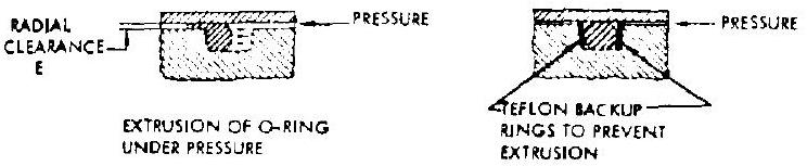 Figure 7-25.-Extrusion of the diametral-squeezetype O-ring under pressure and the application of backup rings.
properties (furnished by the producer) is based on operating conditions such as type of fluid or propellant, pressure, temperature, and type of seal (dynamic or static). 5. Installation of diametral-squeeze-type O-ring seals.-Proper installation of O-rings during component assembly is extremely important to assure an effective seal. Generous chamfers or radii should be provided on all edges and corners in contact with O-rings to minimize the possibility of cutting or scratching during the assembly process. 6. O-ring seals for valve seats.-O-rings can be applied effectively as seals for valve seats (fig. 7-26). The resiliency of the O-ring absorbs shock loads and seals tightly at all pressures, even when some dirt and grit are present in the system. One design problem is to prevent the O-ring from being blown out of the groove. This can be prevented by providing a dovetail O-ring groove in a two-piece valve poppet (see fig. 7-26).
Design of Dynamic Seals for Low-Temperature Services
For cryogenic or low-temperature services, lip-type seals made of elastomer sheets (figs.
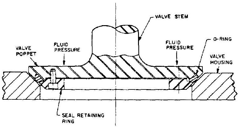 Figure 7-26.-Typical valve seat 0-ring seal design for poppet-type valves.
7-27, 7-28, and 7-29) are used effectively as dynamic seals for moving cylindrical parts and valve seats. This type of seal has been applied successfully at sealing pressures over 2000 psi , and at temperatures as low as . They are also reasonably effective when sealing low-molecular-weight gases such as helium and hydrogen.
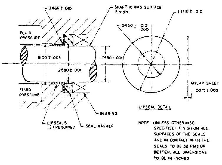 Figure 7-27.-Typical rotating lip-seal design for valve actuator shaft.
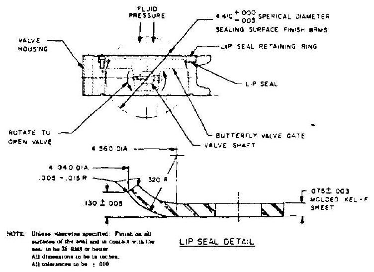 Figure 7-28.-Typical valve seat lip-sealdesign for butterfly-type valves.
The basic design principle of lip seals is to employ the fluid pressure to increase the contact pressure at the sealing surfaces. Due to their lip configuration, the resilience of these seals is maintained even at very low temperatures. Design considerations for lip seals are similar to those for O-ring seals. The design approaches can best be illustrated by examples. Figure 7-27 shows a typical valve shaft rotating lip seal arrangement, including dimensions and surface finishes, for liquid oxygen and hydrogen service. Figure 7-28 presents the valve seat lip seal of a butterfly valve for use with the same riuids. Valve seat O-ring seals (fig. 7-26) made of Kel-F have also been successfully applied in poppettype valves for liquid oxygen. The design of lip seals for piston-type actuators using lowtemperature helium gas as the actuating fluid is shown in figure 7-29.
In liquid hydrogen s , metallic bellows (as shown in fig. 7-30) ...ve been used to a great extent to achieve positive dynamic sealing. However, pressure levels and available space impose limitations on their application.
Design of Dynamic Seals for High-Temperature Services
The metallic bellows (fig. 7-30) is most frequently used as reciprocating-type dynamic seals for high-temperature services. Two types of metallic bellows are distinguished: the hydraulicformed and the multidisk welded type. The former is made of one to three plys of sheet metal and is designed for all pressure ranges. The latter is for relatively low-pressure services and for high flexibility.
A metallic bellows of any type behaves, in part, like a helical spring. The spring rate ( of movement) is a direct function of the
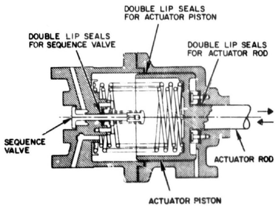 Figure 7-29.-Lip seals for piston-type actuators. Double lip seals seal pressures both ways.
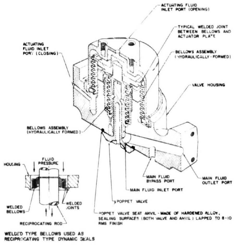 Figure 7-30.-Metallic bellows used as recipro-cating-type dynamic seals in a typical poppet valve for high- and low-temperature services.
alastic modulus, and of approximately the square of the thickness of the material. It is also a function of the outside-inside diameters and of the number of convolutions and their curvature. For maximum flexibility (inches of stroke/lb of load), a minimum inside diameter combined with a maximum outside diameter should be used. Also, material thickness (within stress limitations) and modulus of elasticity should be minimum.
Generally, bellows design data, such as stock size, allowable working pressure, spring rate, materials and service temperature, are supplied by the manufacturers. Important design considerations are discussed in the following:
- Application of pressure.-When a bellows is subjected to a differential pressure between interior and exterior, it is preferable to apply the higher pressure to the exterior. This reduces stress, and permits higher pressures and longer life for a given design.
- Provision of mechanical stops. -These should always be provided to prevent extension of the bellows beyond its permissible extended lergth and compression beyond its "bottomed" height.
- Selection of materials.-Selecting of bellows material should be governed by fluid compatibility or corrosion considerations, operating temperature ranges, and spring characteristics. Some high-temperature alloys such as stainless steels, Monel, Inconel, and Hastelloy B have proven suitable.
- Effective area.-This is that area which, when multiplied by a change in bellows length, yields the actual displaced volume. This area can be approximated by
Bellow effective area
- End attachment.-Typical welded joints for the end attachment of bellows are illustrated in figure 7-30. Silver brazing and soft soldering can also be employed for low-temperature services.
A typical design of a rotating-type dynamic seal for high-temperature services is illustrated in figure 7-31. The dynamic sealing is achieved through the spherical mating surfaces between the graphite seal ring and the steel shaft collar. The contact force of the sealing surfaces is maintained by the shaft thrust spring. Any misalinement between the thrust bearing and the shaft is compensated by the spherical seal face and side movement of the seal ring. This seal arrangement has been applied to a turbine hot
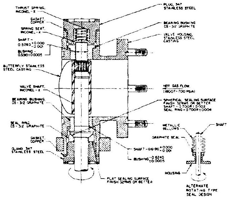 Figure 7-31.-Turbine hot gas throttle valve with typical rotating-type dynamic seals.
gas throttle valve which was operated successfully at temperatures ranging from to at pressures up to 700 psia . An alternate design is to attach a flat-face graphite seal ring to the end of a metallic bellows which is welded to the shaft (fig. 7-31). Here, the shaft misalinement is compensated by the flexibility of the bellows.
The sealing of valve seats for high-temperature services is usually achieved by metal-to-metal contact, as shown in figures 7-30 and 7-32. This seal design has two basic requirements. Firstly, a finish of 10 rms or better is required for the sealing surfaces. Secondly, a high-enough unit loading must be applied to create a compensating deformation of the sealing surfaces and to achieve the intimate contact required to overcome manufacturing tolerances, distortion of the
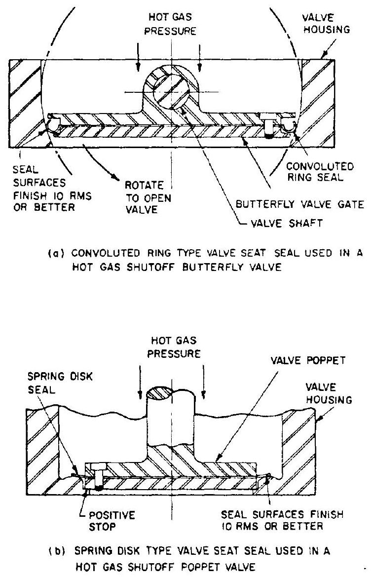 Figure 7-32.-Valve seat seals for high-temperature services.
valve parts due to temperature, internal stress, and mechanical loading of the mating parts.
Figure 7-32(a) shows a convoluted-ring-type valve seat seal used in a hot gas shutoff butterfly valve. Depending upon the specific application, the convoluted ring may be made of hightemperature alloys such as Inconel-718. The rings effect a leakproof seal in the closed position, since the upstream fluid pressure tends to expand the convolute and produces a high contact unit force at the sealing surfaces. The curvature of the convolute ring tends to maintain a continuous contact with the valve seat. Figure 7-32(b) presents a metallic-spring-disk-type valve seat seal used in a hot gas shutoff poppet valve. Again, the upstream gas pressure produces a high contact unit load on the sealing surfaces. The valve seat has a curved contour which effects a continuous contact with the flat face of the seal disk.
Sealing Specifications
The degree of sealing (or the allowable leak rate) is a very important specification which will dictate the type of seal to be selected for a specific fluid-flow-control component design. The basic reference for leak rates is Specification MIL-S-8484. It states that a Grade A seal, the highest quality seal, shall have a leakage rate not to exceed 1 standard cubic centimeter of air/year/inch of seal at a pressure differential of 1 atmosphere. This corresponds to a leakage rate of of seal. It is a design assumption that any seal leak rate below or equal to this value is considered zero leakage. For many applications, higher leak rates are permissible. For instance, a check valve may be specified with a leak rate of 5 scim's (standard cubic inches of gas per minute). This is still a relatively tight specification.