7.15 DESIGN OF MISCELLANEOUS VALVES
Check Valves
The prime function of check valves is to allow fluid flow in only che direction. There are two basic check valve types: the poppet and the swing-gate type. The selection depends to a great extent on application. General design considerations for check valves are- (1) Type of fluid and its pressure and temperature (2) Required flow capacity (3) Allowable pressure drop (4) Allowabls rate of leakback (including zero leakage) (5) Space envelop and line connection (6) Simplicity of construction
Figure 7-69 presents the design of a typical poppet-type check valve. light, compression return spring normally holds the poppet in the closing position. This prevents any possibility of fluid leaking back. When fluid pressure is introduced upstream, the poppet will open against the return spring. Because of their relatively high-pressure drop, check valves of this type are used only in low-capacity services. Either elastomer O-rings or metal to metal seals are used.
Figure 7-70 presents a swing-gate-type check valve. The valve cousists of two elements: the inlet and the outlet body. The swing gate is secured to the inlet body. A torsional-type return spring holds the gate in the closing position. Swing-gate check val as minimize pressure drop. However, positive sealing against backflow is more difficult. In some applications,
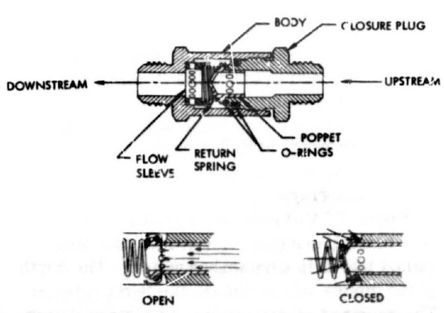 Figure 7-69.-Typical poppet-type check valve.
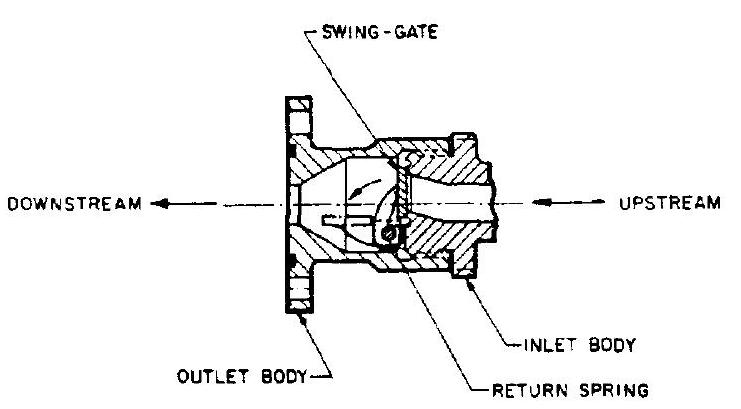 Figure 7-70.-Typical swing-gate-type check valve.
orifice holes are drilled in poppets or swing gates to allow a controlled backflow for specific control purpose.
Burst Diaphragms
When positive, hermetic sealing is essential, in fluid-flow systems burst diaphragms are used. They are especially useful in storable liquid propellant engine system applications; they also serve as safety valves to prevent excessive pressures, or to initiate flow at a predetermined pressure. Burst diaphragms can be ruptured either by the upstream fluid pressure or mechanical means. General design considerations for burst diaphragms are- (1) Type of fluid and its corrosive characteristics (2) Duration of storage (especially with corrosive storable liquid propellants) (3) Method of diaphragm installation in duct or valve body (4) Method of rupture (upstream fluid pressure or other means) (5) Burst pressure level (if upstream fluid pressure is used) and its tolerance; environmental temperature effects (6) Retention of the diaphragm after rupture (no metal particles must be ejected) (7) Allowable pressure drop across the burst diaphragm Figure 7-71(a) presents a typical flat-disk type burst diaphragm. A V-groove has been coined into it in a horseshoe pattern. The depth of the groove will determine the burst pressure. The uncoined section serves as a hinge during rupture and as a retainer. The diaphragm can be
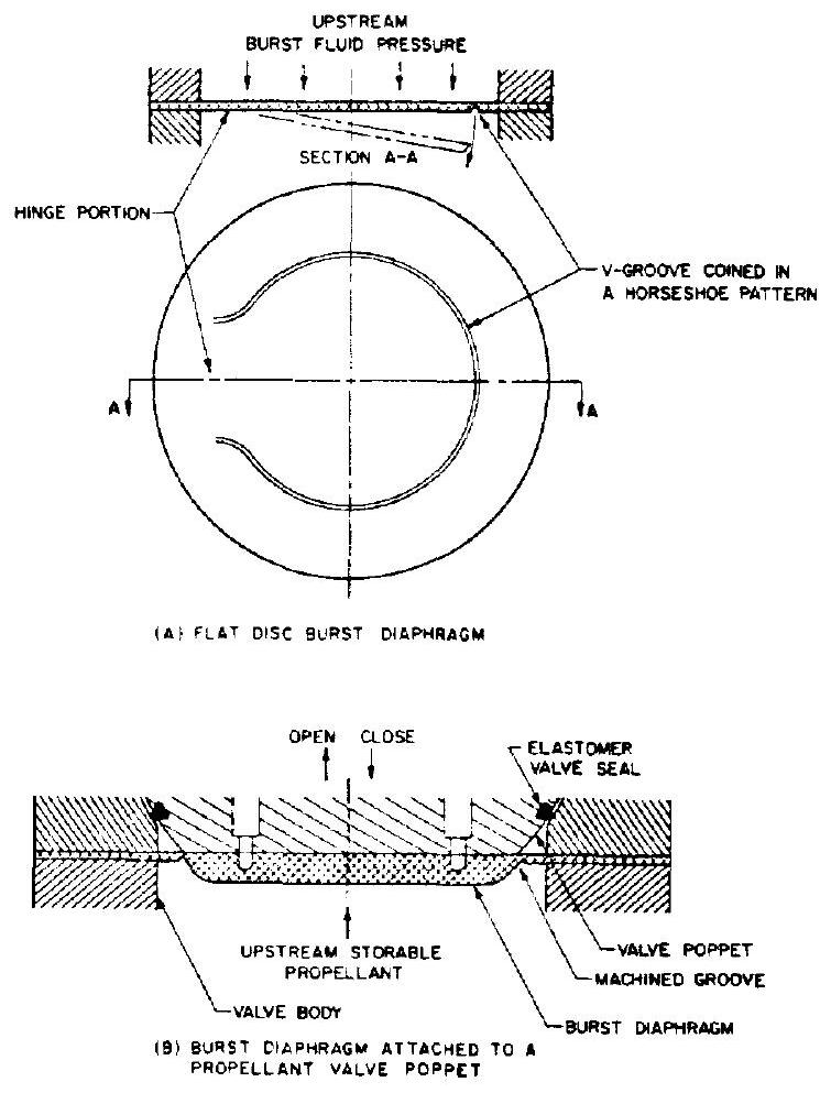 Figure 7-71.-Typical burst diaphragm designs.
jointed to the duct by welding, brazing, or bolting. This design has been satisfactory for many applications.
Figure 7-71(b) presents a poppet-type, storable propellant valve with built-in burst diaphragm. The latter assures a positive, hermetic seal of zero leakage during long storage periods; it also protects the elastomer seal of the valve seat. Rupture of the diaphragm occurs during valve opening, either from valve actuation or from upstream propellant pressure. When closing, satisfactory valve sealing is provided by the elastomer seal only.
Burst diaphragms are made from a wide variety of metals. Annealed aluminum alloys such as 1100-0 and 6061-0 are among the most easily controlled. Burst diaphragms rupture in a combination of shearing, bending, and tearing. The exact burst pressure of a specific diaphragm design can only be evaluated experimentally. Variations of material ultimate strength have a pronounced effect. Consistency of the desired diaphragm burst pressure level will be greatly enhanced by the following precautions in manufacturing and quality control: (1) Grinding of raw sheet or diaphragm to insure uniform and accurate thickness (2) Close control of groove depth, by precision coining or machining, and by stress relieving before and after coining (3) Continuous testing of the diaphragm material for hardness (4) Close control of the clamping pressure with bolted diaphagms (5) Close control of the welding or brazing processes to minimize heat effects (6) Proper dimensioning of diaphragm thickness and groove depth to allow for corrosive effects of the propellant during storage It is possible to hold burst pressure variations of a specific diaphragm design to within percent for diaphragms of over 1 inch diameter and design burst pressures greater than 300 psi . For diaphragms of smaller size and lower burst pressure, this tolerance may increase up to percent.
Explosive-Actuated Valves
In certain applications, a valve may only be required to operaia once (to either open or close). In these cases, explosive-actuated valves provide the smallest possible size and weight. Sirce the power of the explosive actuation is virtually unlimitsd, a rigid, hermetic zero-leakage-type seal can be used with this type of valve.
Figure 7-72 presents a typical explosive actuated pilot valve developed and produced by the Conax Corp. The actuator of this normally closed valve consists of an explosive c'arge " A ," and a ram " B " including a shearing head
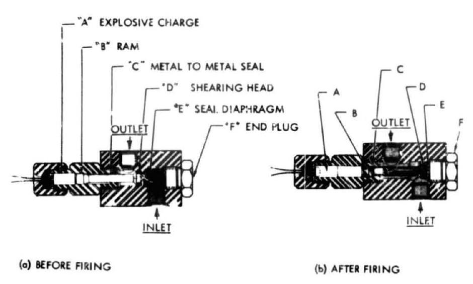 Figure 7-72.-Typical explosive-actuated pilot valve.
"D." The seal of the valve is provided by a solid motal diaphragm "E," machined as an integral part of the valve body. Upon an electrical signal the explosive charge detonates and drives the ram forward to cut out the seal diaphragm as a single piece of metal and hold it firmly against the end plug "F." Ram "B" has a tapered head, which rams into the guide-hole edge and causes a perfect metal-to-metal seal at point "C." This prevents contamination of the working fluid with gases from the explosive charge. The input current required for this valve is about 0.5 ampere; actuation of the valve takes about 0.002 second.
Explosive cartridges may also be used to actuate valves of larger size, such as the main propellant vaives. In the form of threaded plugs, they can be attached to the valve actuator ports in lieu of pneumatic lines. For maximum reliability, two separate cartridges are often installed. The pressures produced by the cartridges range from approximately 2000 to 10000 psi . The valve designer will have to determine the required pressure and volume of the gases at the end of the actuator stroke, which then serve as the specification to the cartridge supplier. cretainthe
- cultumentrit 1