4.6 GAS-GENERATING DEVICES
In liquid propellant rocket engine systems, gases are required to power the propellant feed systems and other subsystems. Bottled compressed gases such as helium can be employed for these purposes; however, the use of higher temperature gases generated by suitable devices gives much higher overall system performance. Gases at temperatures ranging from to have been generated for pressurizing propellant tanks. Gases in the range from to are used to drive gas turbines for pump-fed systems. Where ever possible, the engine system primary propellants are used for gas-generating purposes in the interests of overall system simplicity. However, for certain applications, such as for a pressurized gas-fed system or for starting a turbopump-fed system, high-pressure propellants other than those tapped off the primary system are required to supply the gas-generating systems.
Most operational engine systems use special devices for gas generation. However, tapping hot gases from the main chamber has shown promise for certain applications. The following is a list of design objectives for operational gas generators: (1) Ability to produce gases safely, with required properties (temperature, pressure, nonexplosive) in a compact unit, at the required flow rate. (2) Ability to start and stop smoothly, without abrupt temperature surges, pressure oscillations, or overflow of unburned propellants. (3) Ability to operate over a wide range of propellant flow rates and (in the case of bipropellants) mixture ratios, and to respond closely to the control system. (4) Ability to maintain safe shutdown without complicated purging and draining systems. (5) Ability to restart safely (restartable engine systems only). Additional design requirements depend on the particular engine system involved.
Gas generators can be classified according to the propellants employed: (1) Solid propellant systems (2) Liquid monopropellant systems (3) Liquid bipropellant systems.
Solid Propellant Gas Generators
Solid propellant gas generators are applied to liquid propellant engine systems for limitedduration applications only, such as for turbine spinners for engine start, or as pressurants for short-duration pressure-fed systems. The temperature of the gases generated by solid propellants is generally in excess of and is not suitable for uncooled components over extended durations. Diluents can be used with a loss of basic simplicity.
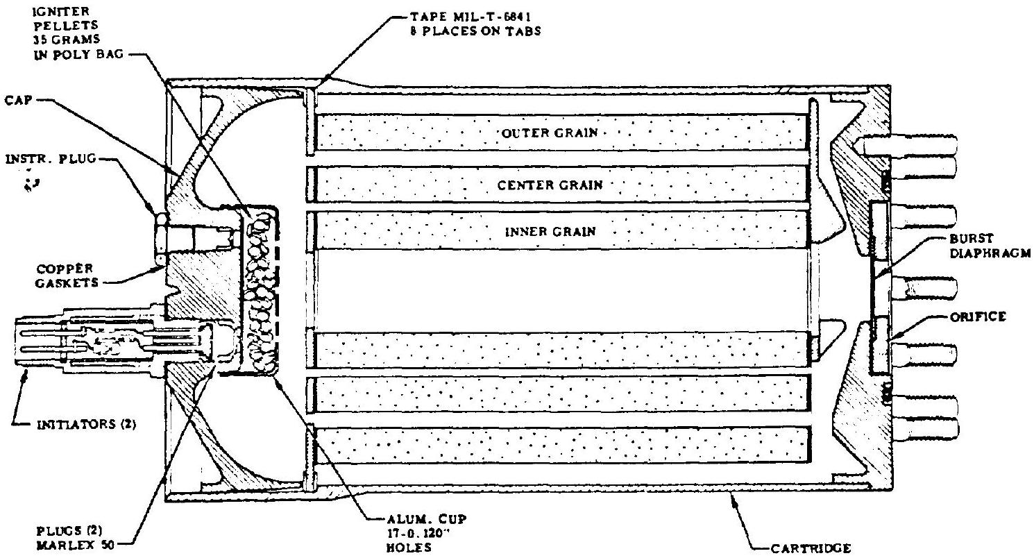
Figure 4-49 shows the typical design of an operational solid-propellant gas generator used to supply power to the turbine for engine start. It is built in the form of a cartridge that bolts to a flange at the liquid bipropellant gas generator (shown in fig. 4-51). The particular cartridge shown is a disposable type that cannot be reloaded and reused. Upon an engine start signal, two initiators or igniters set off solid propellant combustion.
Twenty milliseconds after start, the solid grain produces a gas-flow rate of approximately 4.68 pounds per second. It will maintain this flow rate for approximately 1.0 second. This gas generator operates at and at a chamber pressure of 1000 psia . The product gas renders an approximate characteristic velocity of . A burst diaphragm located just upstream of the gas generator orifice is used to seal the unit during storage. It is ruptured by the increased gas pressure at start. Body and end cap are made of 4130 steel.
 Figure 4-49.-Disposable solid propellant gas generator (SPGG).
Solid propellants burn uniformly at the exposed surfaces at a rate which is primarily a function of the temperature and the pressure of the surrounding gases. The correlation for a given propellant can be expressed as
where propellant linear burning rate, in/sec constant representing the linear burning rate of a given propellant, at a given initial temperature and a chamber pressure of 1000 psia chamber pressure, psia constant allowing for the sensitivity of the propellant burning rate to changes in pressure, at a given temperature. The weight flow rate of a solid propellant gas generator can be calculated by
where weight flow rate through gas generator, lb/sec burning area, in propellant density, It can be seen that a solid propellant gas generator of constant flow requires a propellant grain design which assures constant burning area. The correlation between , and gas generator orifice area can be expressed as
where gas generator orifice area, constant characteristic for a given propellant at a given temperature.
Liquid Monopropellant Gas Generators
Monopropellants such as hydrogen peroxide ( ) and hydrazine ( ) have been used as gas generants in many applications. They permit a simple generator system and do not require mixture-ratio adjustments. The advantage of these systems is that they are relatively easy to control and that the gases are generated at predictable temperatures. However, unless the monopropellant is also employed as one of the engine system main propellants, the monopropellant gas generator system introduces a third propellant often requiring special handling and tankage.
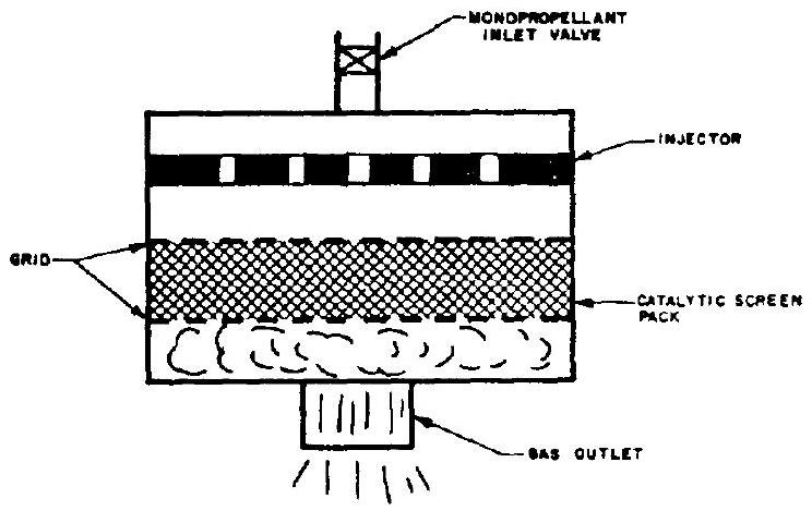
Figure 4-50 shows the schematic of a typical monopropellant gas generator using 90 percent hydrogen peroxide. The catalytic screen pack or bed consists of alternate layers of stainlesssteel mesh and silver-plated brass wire screens secured by perforated end plates or grids, which are applied with a preload of approximately 1000 pounds per square inch of bed crosssectional area. The length of the catalytic bed generally ranges from 2 to 3 inches. The allowable design throughput, that is, propellant flow rate per unit cross-sectional area of catalytic bed, is about . The propellant pressure drop across the bed can be approximated by
where
 Figure 4-50.-Schematic of monopropellant gas generator.
Sample Calculation (4-9)
A hydrogen peroxide monopropellant gas generator attached directly to the inlet flange of a turbine has the following design data: Turbine inlet pressure, 340 psia; total turbine nozzle throat area, . Assume a value of for 90 percent and catalytic bed design constants and . Determine the gas generator propellant flow rate , catalytic bed area, and pressure drop after 480 seconds of accumulated running time.
Solution
Gas generator pressure = turbine inlet pressure . Equivalent gas generator throat area total turbine nozzle throat area . Substitute into equation (1-32):
Propellant flow rate Use a design value for catalytic bed throughput, , of
Substitute given data into equation (4-49):
Liquid Bipropellant Gas Generators
This gas-generating system is used more widely in liquid rocket engine systems than any other, since it makes use of the primary rocket engine propellants. Bipropellant gas generators react in the same manner as the main thrust chamber, except that the oxidizer-fuel-mixture ratio will be adjusted to yield the desired gas temperatures and chemical properties. The gases generated may be either fuel rich or oxi- dizer rich, depending on the propellant combination. Oxidizer-rich gases tend to accelerate erosion of structural members, while fuel-rich gases continue to burn with ambient air after discharge, requiring special measures to prevent damage.
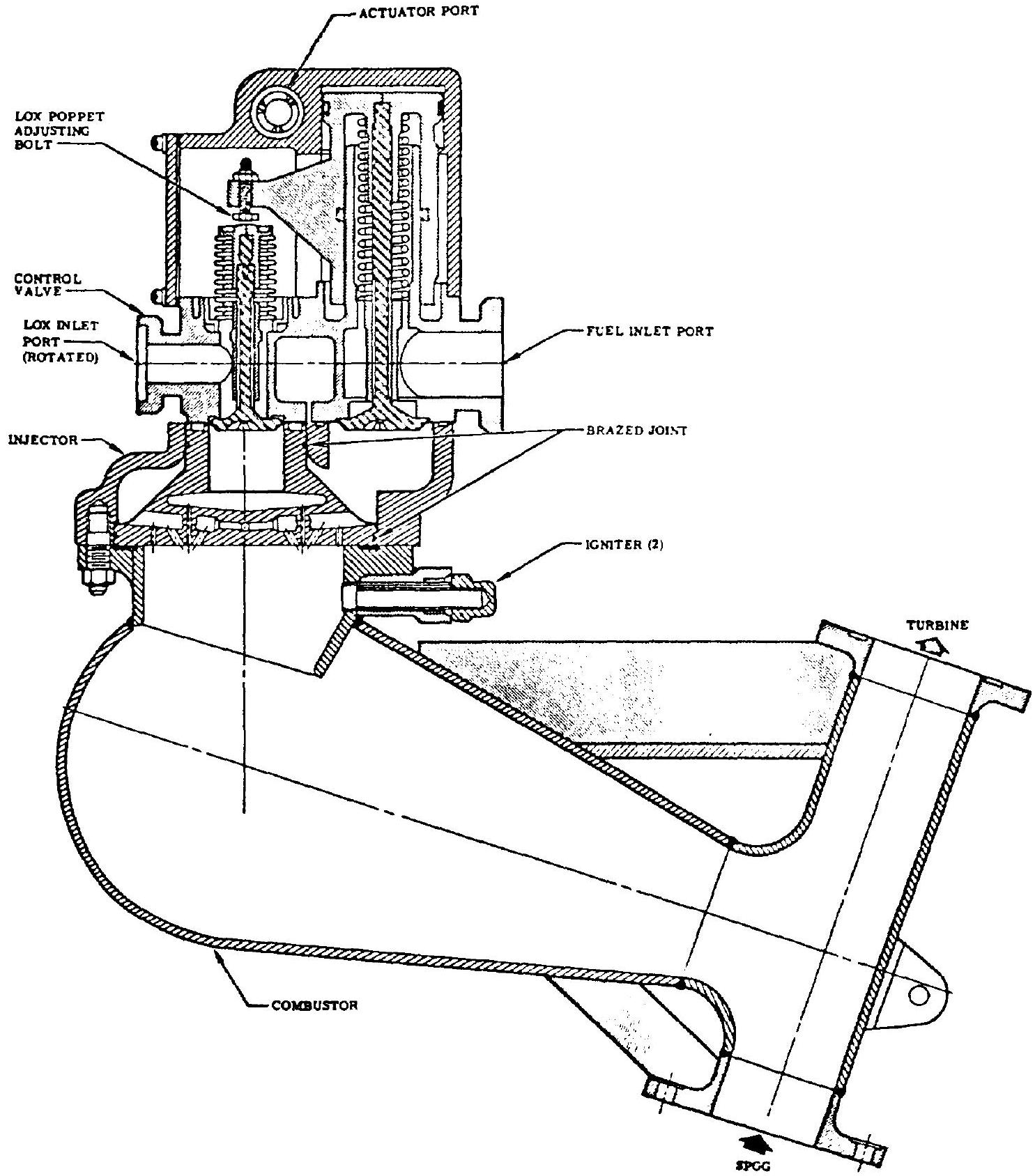
Figure 4-51 and table 4-2 describe a typical liquid bipropellant gas generator system. It is designed to produce hot gases using primary engine propellants ( ) for driving the turbine of a pump-fed system. The control system consists of two normally closed, linked poppet valves that control the flow of propellants to the gas generator injector. The valve assembly includes an oxidizer strainer, oxidizer poppet, fuel poppet, timing orifice, actuating piston, and valve main body. The valve assembly is actuated by gas pressure which forces the piston on the fuel side down to open the fuel poppet. A yoke integral with the piston actuates the oxidizer poppet. The valve design, through a combination of manifold volumes and LOX poppet adjustment, effects a slight oxidizer lead to prevent detonations, and a fuel-rich cutoff to eliminate the possibility of turbine burning. The propellants flow through the poppets to the injector and into the gas generator combustor, are mixed, and burn within the inner chamber and combustor body. Ignition of the propellants is accomplished by two pyrotechnic igniters. A gas duct with two flanges opposite to each other is located at the end of the combustor body. These flanges connect with the solid propellant gas generator turbine spinner and the turbine inlet.
The basic design parameters for bipropellant gas generators are similar to those for thrust chambers. The total throat area of the turbine nozzles may be considered to be the equivalent throat area of the gas generator combustion chamber. In calculating combustion chamber characteristic length , the volume between injector and turbine nozzle throats is used, with a correction factor allowing for the specific design configuration. Because of temperature limitations of the turbine construction materials, gas generators are rarely operated at gas temperatures higher than . In most designs no cooling is provided for the combustion-chamber wall and other surfaces exposed to the hot gases.
 Figure 4-51.-Liquid bipropellant gas generator.
The maximum available energy per pound of gas generator propellants is obtained when the products of combustion are expanded isentropically through a supersonic nozzle to ambient pressure. This quantity of energy is termed the available energy content , and is expressed by the correlations in equations (6-16), (6-17), and (6-18).
TABLE 4-2.-Operating Characteristics of a Typical Liquid Bipropellant Gas Generator System, as Shown in Fig. 4-51
| Oxidizer | Liquid oxygen |
|---|---|
| Fuel | RP-1 |
| Total propellant flow rate | |
| O/F mixture ratio | 0.342 |
| Oxidizer flow rate | |
| Fuel flow rate | |
| GG chamber pressure (injector end) | 612.1 psia |
| GG chamber temperature | |
| Oxidizer-side pressure drop of line, valve, and injector | 114 psi |
| Oxidizer side pressure drop across orifice | 121 psi |
| GG oxidizer supply line takeoff pressure (total at main oxidizer pump discharge) | 846 psia |
| Fuel side pressure drop of line, valve, and injector | 216 psi |
| Fuel side pressure drop across orifice | 80 psi |
| GG fuel supply line takeoff pressure (total at main fuel pump discharge | 907 psi |
Thrust Chamber Gas Tapoff Systems
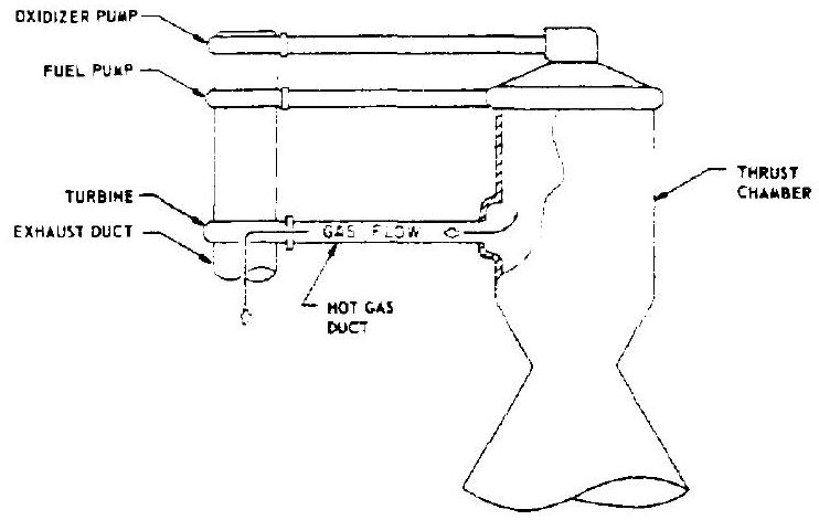
With these systems, combustion product gases are bled from the main thrust chamber and ducted to the turbine, where they are used as the working fluid. This arrangement eliminates the need for a separate gas generator system and contributes significantly to the simplicity and its reliability potential of the engine system. The technique has been successfully developed by North American Aviation's Rocketdyne Division and appears to be particularly promising for hydrogen engines requiring throttling. Figure shows a schematic of a tapoff system.
In a separate gas generator system, gases are produced and "tailormade" for turbine-power purposes only, with the benefit of relatively high liquid supply pressures. In a tapoff system, the bulk of the extremely hot gases of the main chamber would not be suitable as the turbine drive fluid, in view of the limitation of the turbine construction materials. It has been successfully demonstrated, however, that by withdrawing chamber gases from the boundary zones only, and through proper shaping and location of the bleedports, any desired turbine inlet temperature (usually less than ) can be reliably and repeatably produced, for a given thrust chamber and injector design. The bleed gases thus withdrawn have been found to possess thermodynamic properties comparable to the products of a liquid bipropellant gas generator utilizing the
 Figure 4-52.-Schematic diagram of thrust chamber gas tapoff system.
same primary propellants. However, a tapoff turbine must be designed to operate at an inlet pressure lower than the thrust chamber pressure. Furthermore, a tapoff engine system will require some sort of simple starting device, such as gas spinner. With the aid of a hot gas regulating valve placed at the turbine inlet, hydrogen tapoff engine systems have been successfully throttled to thrust ratios of or better.